Silvio
Well-known member
Hi everyone, here I am presenting a tutorial and explaining my hard work in building a successful working SMPS. I being a newbie myself in this field of work had to learn things the hard way and the way to it all is explained in the PDF attached. All is found in it so one can replicate it. I hope the information included will be of help to new comers.
Introduction
Dear all, I am a newbie in smps and here I am going to explain the hard journey in building a successful smps based on Borysgo2 design. I am a hobbyist and I am also a licensed radio armature. I have a basic knowledge in electronics and I am not an expert in anyway in this field. Building these types of power supplies always fascinated my taught and I tried for the first time to build one from scratch. First of all I made some research and read a lot in the forums on DIYSMPS.COM which was a great help to me in achieving a lot of information. I have been looking a lot in the forums and what other people share on this site. I also asked questions to the gurus here, and some of them where very helpful especially MicrosiM and also Wally. Success took a bit of a long way and burning about 26 mosfets and also quite a few chips, but I will explain why later on. I had no oscilloscope and could not see what was actually happening. I must stress that this is a must here otherwise disappointment will ensue for sure. Care in every way has to be taken here especially dealing with mains. HIGH voltages are present ranging in the 300 volt region and are LEATHAL and can easily KILL YOU. Some form of isolating transformer will give you good protection although care should be taken here as well as SMPS do not joke when they blow and at times they are dangerous not to mention spectacular. The forum page presented by diysmps.com regarding Necessary Equipment's needed for SMPS development. The information here is very helpful and easily understood. So please follow these rules.
IR2153 Chip
The Circuit is based around the IR2153 chip which is a mosfet half bridge driver. It also has a built in oscillator which can be set with a capacitor and resistor to relatively a wide range of frequencies. Unfortunately it does not have a soft start and this has to be catered for otherwise problems will occur when charging the main secondary caps or perhaps started on load. The internal mosfet drivers can sink a current up to around 150-200ma and can drive medium power fets, however driving large fets in the 20 amp range the chip needs to be enhanced with a current amplifier on the HI and LO outputs.
Circuit design requirements for audio
The requirements needed are as follows:
1) Main secondary output for powering an amplifier with single or double voltage to suit.
2) An auxiliary winding for powering a preamp stage with a double output voltage of around 0.5 to 1 amp.
3) Another auxiliary winding for powering the power supply itself of around 500ma and an optional auxiliary for powering a cooling fan. This can be omitted if not needed.
4) A soft start to limit inrush current on switch on.
5) Some kind of delay to wait for the bulk caps to charge before oscillation of the IC commences.
6) A current limiter, or better with a short circuit protection.
Borisgo 2 design
Well the author of this circuit included a constant current source feeding the input of the chip at start up this makes things stable and eliminates the need of the large 27K resistor usually used. He did it in a very clever way such that firstly the constant current source will charge up slowly C3 giving time for the bulk caps to charge up as the threshold voltage is reached (9 volts) the chip starts oscillation and the mosfets start giving power to the transformer. A single turn winding around the trafo energises enough voltage to the gate of a triac TR6 which is now shorting the 15 ohm thermistor (this limits inrush current to bulk caps) thus reducing voltage drop and un-necessary heat. This way a common resistor can be placed instead of the thermistor as this is only active for 1 or 2 seconds. A current limiter is also included in a clever way as it senses the ripple voltage on the dc blocking capacitor C11 feeding the mid point on the mosfets. This is coupled by C10 and R10 amplified by a small transistor TR3 which in turn pulls the supply feeding the chip via an LED hence switching it off and re-start when the excessive load is removed. This also takes care of the fets when starting the supply on load and charging also the secondary capacitor bank.
Re-design
The PCB was re-designed by myself as I had to modify it to suit my needs. I do not know how to use eagle software or any other form of pcb design tool but I know how to use Microsoft publisher quite well and made my PCB with it, well it takes a lot of time to do as every line, circle, oval etc had to be placed in the right position and taking care of the measurement of every component. It is rather a lot of hard work and time involved but where there is a will there is a way.
Modification from original
Well modification had to take place regarding the Trafo footprint, capacitve coupling instead of the current transformer for overload protection and also the diode bridge as I used 3 double common anode fast switching diodes. I bought 50 of these so I got plenty of them. I modified the PCB to take these instead of 4 single diodes. I will show later how they are hooked up. I also had to change the size of the resistor footprint as these where of 1/8 watt instead of 1/4 watt. Which I have a good store of them in my workshop. 1/8 watt resistors are hard to find locally as well
<--- The rest of the information's in in the PDF file below---->
Please comment and share your work if you benefit from this hard work
View attachment SMPS 350 watts RMS.pdf
Attachments
-
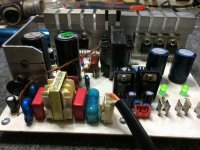 IMG_0212.JPG1.8 MB · Views: 821
 -
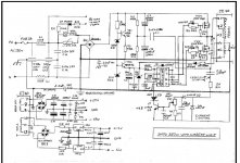 SMPS_Schematics.JPG105.7 KB · Views: 1,445
Last edited by a moderator:
![IMG_0443[1].JPG](https://www.diysmps.com/forums/data/attachments/5/5036-0cf35dca026727a8371a6859522b8a03.jpg "IMG_0443[1].JPG")
![IMG_0441[1].JPG](https://www.diysmps.com/forums/data/attachments/5/5038-8b28ff19a4fcc83a426fb7792a7a188b.jpg "IMG_0441[1].JPG")
")