Low Power 240V AC SMPS <30W flyback or forward?

I have a question for anybody who has built low power SMPS before and looking to build a small mains 240V powered prototype that could deliver +-12V @ 1A (24W) based on UC3842 and those EI33 core (I know its too big but i got plenty unused). Which would be better 1 switch forward or flyback? Am still weighing the pros and cons of each.

Forward is annoying with its high voltage switch off stress am estimating a 600V device would be needed but flyback seems to require a gapped core due to saturation problems.

Any help is greatly welcome

P.S: Am not eager to buy a laptop power pack and recoil it i won't learn anything proper this way. Am building this from scratch and i might need to build a few of these for my own use

Thanks
 

MicrosiM

Administrator
Staff member
The best thing to look at, that will save you time and money is page 122 of (POWER SUPPLY COOKBOOK) By MARTY BROWN - SECOND EDITION

He shows from scratch with calculations how to make a 65W flyback SMPS using UC3845AN chip


Hope that helps
 
Hi Microsim thanks for the reply i have the book and will have a look at it. I haven't seen any small powered flyback design around so i think this answers my question to go for flyback
 
Hi Microsim, I've gone through the chapter you mentionned and i've built and excel file for the calculations. Need to get my hands on some UC3844 for testing. I will post details here if anyone is interested. Purpose is mainly as an auxiliary supply for small projects and powering microcontrollers/relays/pre-amps e.t.c
 

MicrosiM

Administrator
Staff member
Good!!

Hi Microsim, I've gone through the chapter you mentionned and i've built and excel file for the calculations. Need to get my hands on some UC3844 for testing. I will post details here if anyone is interested. Purpose is mainly as an auxiliary supply for small projects and powering microcontrollers/relays/pre-amps e.t.c

Very Interesting!, Good luck and keep us updated!
 
Calculations and transformer layout

Hi Microsim, thanks for the reply below are the calculation results:

Controller IC:UC3844

Target OP Voltage: +-12V 1A and 5V 1A with target ripple of 50mV

Input Voltage 90Vac - 240Vac

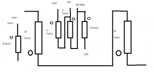
Core Model : EI-33 , AL:861mH/1000T , Primary Inductance: 1mH , Primary Turns:34 Secondary (+-12V) Turns:- 4+4, Secondary (5V) Turns:-2, Vaux(To be implemented later with supply start up):-4

Mosfet Idss>Peak Ip Current:1.21A Vdss>469V (Feel a 600 to 800V mosfet needed here Like FQP6N60)

Rectifier above 1A and greater than 90V

Output Capacitance 470uF 25V X3 or 220uF 25V x6 two one for each output rail (360uF Min from calculations for each output)

Input Capacitor: 100uF 400V

Attached is transformer layout:TRansformer Turns layout.jpg
 
Last edited:
Am changing the design after second thought to build a 12V 5A PSU to power my led UV exposure box i will be posting the new calculations soon
 
Experimenting with IC

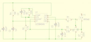
I've experminented with UC3842 and UC3844. The annoying thing with these ic's is that Max duty cycle is limited by RC which needs to be calculated before hand. The circuit is the following: UC3842 test circuit.jpg
 
HI Microsim i've got the IC to run under very low voltage 16V and managed to get 50% duty cycle. I am planning to use a supply startup scheme and have an auxilary winding to power the SMPS.

The startup is basically the same as in Marty Brown's diagram for his 65W offline flyback.\
Do you have any experience with these supply start up and are there any necessary precautions needed? Thanks

P:S: I will post the final schematic here later today.
 

giololucas

New member
HI Microsim i've got the IC to run under very low voltage 16V and managed to get 50% duty cycle. I am planning to use a supply startup scheme and have an auxilary winding to power the SMPS.

The startup is basically the same as in Marty Brown's diagram for his 65W offline flyback.\
Do you have any experience with these supply start up and are there any necessary precautions needed? Thanks

P:S: I will post the final schematic here later today.

It´s nice to see your work in a different topologie. We have a lot smps in half, full or push-pull on the internet ( most we don´t know if work, but...)
Flyback topologie is hard to deal (In my particular opinion. I had some fireworks in past :( ), reset winding and core´s saturation are challenging points.
I´m following your posts.
Good luck!
 
Last edited:
Hi giololucas thanks for the reply. I'll see how things go with this project. By the way slightly off topic question does your IR2153 project use a supply bias start up or powerd by transformer?
 

giololucas

New member
Hi giololucas thanks for the reply. I'll see how things go with this project. By the way slightly off topic question does your IR2153 project use a supply bias start up or powerd by transformer?

Hi zeus.
It use a separate power supply. Now I´m using a PC SMPS.
For 2nd prototype will be a 50/60Hz 15V x 300mA standard transformer in a Auxiliar Board.
Power sequence will be:
When connected to mains AC auxiliar xformer ON and IR always running. EVEN with switch OFF.
When switch is turned to ON position, it charges mains caps via 4r7 thermistor and supply is delivered to mosfets.

This is the same sequence which I´m doing now, I leave IR running and turn on and off removing the power cord.
 

Attachments

  • image2011-09-21-143112.pdf
    140 KB · Views: 217

MicrosiM

Administrator
Staff member
Hi zeus.
It use a separate power supply. Now I´m using a PC SMPS.
For 2nd prototype will be a 50/60Hz 15V x 300mA standard transformer in a Auxiliar Board.
Power sequence will be:
When connected to mains AC auxiliar xformer ON and IR always running. EVEN with switch OFF.
When switch is turned to ON position, it charges mains caps via 4r7 thermistor and supply is delivered to mosfets.

This is the same sequence which I´m doing now, I leave IR running and turn on and off removing the power cord.


This method will make your mosfets blow for no reason in the near future. any time, any minute, without warning.

IR2153D is very tricky
 

giololucas

New member
This method will make your mosfets blow for no reason in the near future. any time, any minute, without warning.

IR2153D is very tricky

It´s true. This IC is very tricky, I blew 2 mosfets and controler board doing:
Mains caps charged then start the IR, booooomm!:"::
But I´m resisting in change the controler to a classic PWM like tl494 or sg3525 + a IR2110 + soft start resistors and relay...
It´s a question to think about.
 
Controller Schematic

Hi this is what the controller currently schematic looks like:UC3844 SMPS.JPG. Am on my way to build it on prototype board. All compoenets have been gathered and transformer wound. I'll update the schematic and keep posted as i move ahead
 
Complete Schematics layout and waveforms

Hi just rebuilt the unit for 12V 4A.

Main core is EI-33 AL 3980 nH/N

Primary 12 Turns for 0.61mH Currently 0.7mH

Secondary Main 1 Turn and secondary for auxiliary supply is 1 Turn

Designed for 90-240Vac input voltage

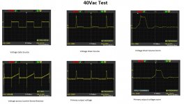
Current Schematic:Complete UC3844.JPG Waveforms: UC3844 40Vac test.jpg

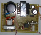
board layout:UC3844 Layout.jpg

I have tested the unit and captured above waveform with 40Vac and 1K resistor on each ouput. Measured output voltage was 31V.The IRF840 is getting very hot could be due to low operating voltage but am not sure.
If Microsim or anybody could please conclude if things are on the right track with the waveform shapes its my first time with this topology. The ringing can be damped with RC snubber but what more is wrong is where i need help.

Thanks
 
Last edited:
Its only after posting that i had time to look at the waveforms, i will replace the IRF840 with some SSS6N80 which i hope i can get here. i got some SSS6N60 handy but i doubt they will do for the job. I've entered 40Vac as lowest and max input ac in my calculation sheet and it comes out that the worse case peak input current is 6.6A and 1.5 A avg. currently my transformer can supply max 3A @40Vac and i measured 39.1V ac input voltage .The unit was designed for 160mA avg ip current, 470mA highest ip current and 2.09A worse case input current.
I don't know if my conclusions are right about the heating mosfet but i will wait for the wise men to reply
 

giololucas

New member
Any comment is welcome thanks

Hi zeus.
After a look , I had another doubt, may be it will be usefull for you:
When VGS is HI, then VDS should be LOW
And when VGS is low, then VDS should be HI.
But if we look to the waveforms, there it´s a period when VGS is LOW, and VDS is LOW too.
In resume I want to ask is:
Why VDS is ZERO when VGS is ZERO too? Looks very strange in my opinion...
 
Hi giololucas thanks for your reply but i don't get your point about one being low and the other low. BAsically as you send a signal through the Gate terminal of a mosfet it should cause a current flow and cause a voltage to appear at the DS terminals. When you remove the signal from the gate you stop the conduction at DS terminals thats how mosfet, BJT and IGBT ... work.
OR are you referring to voltage reversal that occurs in the transformer when the mosfet has finished charging the transformer inductance? Then this occurs at mosfet switch off and its how flyback work.

I am currently checking some waves from other projects they concide for current waveform but the waves am seeing were made with 110VAc. My feel is that this transformer is saturating badly in this application. I have already replaced the IRF840 by an SSS6N60 heat in mosfet is less after some minutes of operation But output voltage is 43Vdc for 50Vdc input. I could also have a short somewhere in my wires. I have an 1.8" 3315 AL/N2 toroid core taken from a car SMPS I will give this core a try to see how it goes as flyback require gapped core to avoid saturation
 
Top