Low Power 240V AC SMPS <30W flyback or forward?

giololucas

New member
Hi giololucas thanks for your reply but i don't get your point about one being low and the other low. BAsically as you send a signal through the Gate terminal of a mosfet it should cause a current flow and cause a voltage to appear at the DS terminals. When you remove the signal from the gate you stop the conduction at DS terminals thats how mosfet, BJT and IGBT ... work.
OR are you referring to voltage reversal that occurs in the transformer when the mosfet has finished charging the transformer inductance? Then this occurs at mosfet switch off and its how flyback work.

I am currently checking some waves from other projects they concide for current waveform but the waves am seeing were made with 110VAc. My feel is that this transformer is saturating badly in this application. I have already replaced the IRF840 by an SSS6N60 heat in mosfet is less after some minutes of operation But output voltage is 43Vdc for 50Vdc input. I could also have a short somewhere in my wires. I have an 1.8" 3315 AL/N2 toroid core taken from a car SMPS I will give this core a try to see how it goes as flyback require gapped core to avoid saturation

Hi zeus.
I understand that the mosfet works in your circuit this way:
When signal is applied to VGS, then VDS shorts the transformer to GND, like a switch.
Look at the picture I posted. Maybe it will be clearly to understand my doubt.

I´m almost sure that transformer is saturating, because it´s non gap.
Flyback Mosfet makes current flow in one direction only, this makes core magnetize, if you don´t switch current flow in reverse way core goes to saturation.

2 things you can try:
-Put reset zener diodes + resistors across primary, see TOP200Y datasheet (be carefull, fireworks may happen. I did it one time.)
-Use a gap in center lag (your PSU core was used for Half bridge, current must flow in 2 directions). If you use gap, then you will have to add more turns because AL is reduced (I don´t know how much).
 

Attachments

  • doubt.JPG
    doubt.JPG
    124.5 KB · Views: 24
  • Topologia%20de%20fontes%20chaveadas.pdf
    559.2 KB · Views: 107
Hi giololucas thanks for the files i get your point to simplify things with the gap am going for a toroid core i mentionned previously. From there i'll measure the waveforms and see ow they do. Off topic but just to mention i managed to get 2 EI-33 cores with AL>3000 am thinking of building a low power half bridge with them and see how they do but that will be another SMPS project. I'll do the mods i mentionned and post the waveforms here to see if things shape up correctly and also check back the waveform timing in the SMPS textbooks i got
 

giololucas

New member
Hi giololucas thanks for the files i get your point to simplify things with the gap am going for a toroid core i mentionned previously. From there i'll measure the waveforms and see ow they do. Off topic but just to mention i managed to get 2 EI-33 cores with AL>3000 am thinking of building a low power half bridge with them and see how they do but that will be another SMPS project. I'll do the mods i mentionned and post the waveforms here to see if things shape up correctly and also check back the waveform timing in the SMPS textbooks i got

Ok zeus.
I think wave forms will not change a lot with toroid, but, I´m curious to see the modification! Go on!:UP:

EI-33 non gap, half bridge, will work for sure, at least 120W with IRF840s .
I have plans to do a low power with EI-33 too, since I have it here. We can do it togheter in other topic if you want.
But first I want to finish my 2nd prototype 800W (see attached in advance). Prototype is stopped for a while (studying for tests in college :eek:).

I´m still following your steps to learn, and help.
Thank you for your efforts and sharing information.
Good luck with new transformer.
 

Attachments

  • componentes.pdf
    26.9 KB · Views: 97
Hi Giololucas & Microsim thanks for the reply. I tried the toroid i had first with ten turns from ym calc sheet but it was saturating completely. I experimentally tried 30 turns and everything was ok. I did a quick measurement with a dirty scope i had, things seemed ok and mosfet heating was gone.

I also puposefully added 40 turns secondary and overloaded the output with a 47R resistor the current protection was kicking in with a sort of "hiccup" mode.

I need to recheck my calculation sheet and correct mistakes , rewind the core properly and take clean measurements with the big scope. Things seem to be back on track thanks gilolucas for the tips.

For the EI-33 halkf bridge with IRF840 sure we can do it in another thread i'll be glad to. i have to complete this flyback too before i can go for another SMPS.

thanks for sharing your silk screen i don't want to bother your project but from your layout i would the following:

1) Move Q1 and Q2 at the edge of the board for easier heatsink fitting and
2) move the dc input input filter caps more inside the board and closer.
3) Ensure enough heatsink space for the rectifier. I my half bridge testing running my 100W 4R amp + speaker my diodes did get warm. It could be greater with your power levels
You can check how ludo and microsim have made their PCB and component orientation it can give you some ideas as well. But these are just some ideas. Good luck with your smps hope to see another nice working version here soon
 
Last edited:

giololucas

New member
Hi Giololucas & Microsim thanks for the reply. I tried the toroid i had first with ten turns from ym calc sheet but it was saturating completely. I experimentally tried 30 turns and everything was ok. I did a quick measurement with a dirty scope i had, things seemed ok and mosfet heating was gone.

I also puposefully added 40 turns secondary and overloaded the output with a 47R resistor the current protection was kicking in with a sort of "hiccup" mode.

I need to recheck my calculation sheet and correct mistakes , rewind the core properly and take clean measurements with the big scope. Things seem to be back on track thanks gilolucas for the tips.

For the EI-33 halkf bridge with IRF840 sure we can do it in another thread i'll be glad to. i have to complete this flyback too before i can go for another SMPS.

thanks for sharing your silk screen i don't want to bother your project but from your layout i would the following:

1) Move Q1 and Q2 at the edge of the board for easier heatsink fitting and
2) move the dc input input filter caps more inside the board and closer.
3) Ensure enough heatsink space for the rectifier. I my half bridge testing running my 100W 4R amp + speaker my diodes did get warm. It could be greater with your power levels
You can check how ludo and microsim have made their PCB and component orientation it can give you some ideas as well. But these are just some ideas. Good luck with your smps hope to see another nice working version here soon

Good work.
Other way is to slowdown the frequency and see the best point (less frequency more flux) since you did more turns, then you can determine the saturation of material (be carefull when saturation is reached )
I will wait for measurements, it will be very usefull for everybody here, and a plus for you, the first flyback DIY!

My wish is to build a adjustable 0 to + -30V to use on the workbench, low ripple , stable , protected, digital voltage indicator, digitally controled (LCD), finally a low power but hi-end smps.

About my layout, I will think about your tips, after all, it´s easy and cheaper to change now than after building! Thanks.
 
Last edited:
Hi giololucas thanks for the commnets i'll keep going forward and post my measurements. Since we are sharing info As bench psu am also thinking of building one 30V 5A i was considering SMPS but i prefer to go the old transformer way based on LM723 very afforcable ic. SMPS will radiate into instruments. Take a look at this:http://www.sentex.ca/~mec1995/circ/ps3010/ps3010a.html or if you are used to microcontroller programming you can build a digitally controlled PSU based on microcontroller and with R2R ladder DAC feeding series pass transistors.
 

giololucas

New member
Hi giololucas thanks for the commnets i'll keep going forward and post my measurements. Since we are sharing info As bench psu am also thinking of building one 30V 5A i was considering SMPS but i prefer to go the old transformer way based on LM723 very afforcable ic. SMPS will radiate into instruments. Take a look at this:http://www.sentex.ca/~mec1995/circ/ps3010/ps3010a.html or if you are used to microcontroller programming you can build a digitally controlled PSU based on microcontroller and with R2R ladder DAC feeding series pass transistors.

Ok, we can make a try.
I´m used to program 16f628a.
 
Hi giololucas thanks for the reply but am really eager to go for that LM723 from what i've read many of these 30V 5A regulated bench psu are based on it. that ic was designed in the 60's or so and stood the test of time its still being used. You can google for microcontroller based psu or digitally controlled psu you should get some cool results. Most of them are based on pic 18F or pic 16F877 cause it needs ADC for voltage feedback control and sufficient lines for lcd control and such. There is also a trick in there is that you need a level shifter for you series pass transistors as pics can only ouput VDD not more plus sufficiently closed matched high precision resistors for the R2R DAC to be accurate otherwise you need a good quality DAC. Some industrial models even have a keypad for dialling the voltage which are used on test lines in equipment assembly plants but i've rarely heard of these being used in labs it all depends how it is designed. Given all that complexity thats why am more inclined towards LM723
 

giololucas

New member
Hi giololucas thanks for the reply but am really eager to go for that LM723 from what i've read many of these 30V 5A regulated bench psu are based on it. that ic was designed in the 60's or so and stood the test of time its still being used. You can google for microcontroller based psu or digitally controlled psu you should get some cool results. Most of them are based on pic 18F or pic 16F877 cause it needs ADC for voltage feedback control and sufficient lines for lcd control and such. There is also a trick in there is that you need a level shifter for you series pass transistors as pics can only ouput VDD not more plus sufficiently closed matched high precision resistors for the R2R DAC to be accurate otherwise you need a good quality DAC. Some industrial models even have a keypad for dialling the voltage which are used on test lines in equipment assembly plants but i've rarely heard of these being used in labs it all depends how it is designed. Given all that complexity thats why am more inclined towards LM723

Hi zeus.
LM723 is a nice analogical controler, but I never tried it.
I´m not sure what kind of technology I will choose.... -) because we have too much options, with positive and negs, as you said in the earliers posts.
I´m inclined to use PIC, I´m curious to see microcontrolers managing power.
It´s ok if we made diferent designs, we will get knowledge twice.
Don´t worry, we have time, to build a lot of stuff.... :)
Yet, we will continue sharing knowledge, regardless of chosen design.

Thanks
 
Hi thanks for the reply giololucas sure we can do many projects and share knowledge am emsuring waveforms from half bridge today and will post it as it gets completed. If you really are eager to see microcontrollers managing power take a look at these:
http://www.microchip.com/stellent/i...AGE&nodeId=2524&param=en027097&redirects=SMPS
http://www.microchip.com/stellent/i...&nodeId=1406&dDocName=en539797&redirects=acdc
These are microchip SMPS solutions and reference designs based on DSPIC series
 
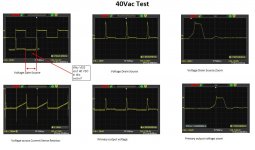
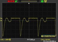
Measured primary transfo waveform

This is what i measured from my primary transformer waveform:40VBLUTO.jpg
with 30 turns. I feel the toroid core am using is not meant for this purpose. With double number of turns the small sort of "sine wave" at the beginning becomes square shaped and i get and overall flat square wave but the fall time remains like in the picture with a rounded botton.Its very far from realistic waves which are obtained from flyback smps.. Maybe it would be a better choice to builld an EI33 based half bridge for my 12V 4A needs than continue to fight with this design.
 

Attachments

  • 40VBLUTO.BMP
    219.4 KB · Views: 54
Last edited:
Hi IGBt thanks fir the link i have already gone through it during my research on flyback smps. I am searching in my junk parts and i found a gapped ETD core. I will give it a try. In case things don't turn out right i already gathered everything i need to build a TL494 EI-33 based half bridge smps
 

giololucas

New member
Hi thanks for the reply giololucas sure we can do many projects and share knowledge am emsuring waveforms from half bridge today and will post it as it gets completed. If you really are eager to see microcontrollers managing power take a look at these:
http://www.microchip.com/stellent/i...AGE&nodeId=2524&param=en027097&redirects=SMPS
http://www.microchip.com/stellent/i...&nodeId=1406&dDocName=en539797&redirects=acdc
These are microchip SMPS solutions and reference designs based on DSPIC series

Great link. But my pic recorder doesn´t support dsPIC! :(
I have to do something more simply.
Thanks.
 

giololucas

New member
Hi IGBt thanks fir the link i have already gone through it during my research on flyback smps. I am searching in my junk parts and i found a gapped ETD core. I will give it a try. In case things don't turn out right i already gathered everything i need to build a TL494 EI-33 based half bridge smps
Since you are not going to a mass production (no costs problem), moving to a Half-Bridge will be quite fast and easy. (no more saturation or reset winding, hell!).
Good luck.
 
Hi giololucas thanks for the reply. Well i bought my pickit 3 clone from ebay from sure electronics i got it with an icsp header board and its affordable. It also supports most of the pic you might need to program. Regarding that flyback could you tell me the core you have used in your experiments? Am starting assembly for the half bridge i will open another thread for it. In case anybody has built flyback SMPS from cores available from ebay or similar sites please tell thanks.
 

giololucas

New member
Hi Zeus.
I used 2 cores for experimentations, both of them didn´t work properly (no good waves, no power transfer, lot of heat in mosfet, and some fireworks !!!:)
First one was EI-33 with 10, 20 or 30 turns in primary, no success. I tried non-gap and gapped. (I destroyed one EI-33, because I did gap with a sandpaper!).
Second core is from a local supplier named Thornton, see datasheet in attached. This second core, is working perfectly in my prototype at 600W, no saturation, Half bridge mode :UP:.

For a while I´m leaving aside flyback topologie too, too much headache, in future I will try it again.

Thanks.
Giolo.
 

Attachments

  • material.pdf
    114 KB · Views: 60
Top