Necessary Equipments needed for SMPS development.

KX36

New member
Regarding isolation transformer use, it is ALWAYS recommended from a safety point of view to isolate the device under test and not the scope when isolation is necessary (which would be when probing the primary side of an isolated offline converter). This means you have to get a transformer that can handle the power of the SMPS so it will be bigger and more expensive than if you were isolating the scope.

Regarding only using 1 scope probe at once, SMPS design is considered to be one of few scenarios where the use of 4 channels simultaneously is frequently required. All channels must be referenced to the same ground otherwise the scope and the device could be damaged, but that's oscilloscopes 101 and is true for any circuit, not just SMPS. If you want to probe the primary and secondary sides of an isolated converter simultaneously, you'll be voiding the isolation, so you'd have to power the SMPS from an isolation transformer in this case.
 

jonfrason

New member
I don't understand this.
My scope is isolated in the power supply, since the PSU is an SMPS with a transformer in between.
What is then the purpose of a isolating transformer for the scope, as it just break the live/neutral?
The earth (by earth i mean the earth from copper spear in house/at the generator) from power outlet is same as scope probes ground.

Do the scope need earth connection to get proper readings? Do the scope use earth to have the proper reference?

Could a solution be to have the scope connected to ground, and remove ground connection on the device being tested?
 

KX36

New member
See my last post. As I said, it's the device under test that needs to be isolated from the mains when isolation is required, not the scope, and that's where the isolation transformer should be.

As you're aware the scope's front end is isolated from live and neutral by its power supply, but the common ground terminal of all the inputs is usually connected to protective earth through the scope's wall plug. Lifting the ground pin on the scope could potentially allow measurements to be made that couldn't otherwise be done, but it won't be safe to do so as there's the possibility that the scope chassis may become life if it has a power supply fault, although the isolation transformer reduces this risk by a small amount, I certainly wouldn't recommend doing this.
 

KX36

New member
As discussed, having a scope floating rather than protective earth referenced may be able to probe the primary side of a power supply without immediately blowing up, but its far safer to put an isolation transformer between the power supply and the wall. Bear in mind that a floating scope probing here makes the whole scope including the probes and any exposed metal part of the mains circuit and a scope usually has far fewer safety features than a multimeter and a lower measurement category rating level and voltage.

Unless of course the scope is designed for power electronics use. e.g. Fluke scopemeter 120 series is cat III 600V whereas bench scopes are usually cat II 300V.
 

rocifier

New member
Thanks for your reply. In terms of the physics behind it, how does adding an isolation transformer make it safer to probe?
 

phaedrus

Member
Hello
Is there any reason for using a 100x probe only instead of 10x.Is it for safety reasons (X10 rated at 300V,X100 rated 2kV) ?
Cheers.
 

MicrosiM

Administrator
Staff member
Hello
Is there any reason for using a 100x probe only instead of 10x.Is it for safety reasons (X10 rated at 300V,X100 rated 2kV) ?
Cheers.


Yes, for safety reasons, as its the first concerns, beside the 10X probe will work or not.
 

km-r

Still a student
Thanks for your reply. In terms of the physics behind it, how does adding an isolation transformer make it safer to probe?

you are electrically isolated from the ground/earth. line mains is "grounded/earthed" somewhere down the line. the ground/earth is like a high Mega- or Giga- ohm resistor that allows current flow from the grounding/earthing point, across your body, and into the spot where you touch a "live/hot" side of equipment. and of course, current kills.

by using an isolation transformer you basically add more resistance practically isolating you from ground/earth.

i use two back-to-back 14v transformers [from car battery chargers] for low power work/troubleshooting with option to use 100W incandescent or 400W halogen bulb as "fuse". i havent worked on higher wattage so far...


regarding the oscilloscope, i dont have one. i use the uni's scope but its too much of a hassle to request permissions. im saving up for a DSO203 because im a cheap bloke and my allowance isnt that much. but ive seen it can display good square waves up to a few MHz so i guess it can be a good workable solution for <100KHz working frequency.
 

Silvio

Well-known member
Advice needed regarding isolating transformer setup to power oscilloscope

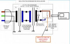
Hi everyone I need some advice regarding the setup of the isolating transformer. This is constructed with 2 X 50va step down transformers hooked back to back. What I am not sure of is whether I should connect the ground pin going to the oscilloscope or not if I had to power the smps directly from the grid. Please take a look at the schematic below.
Help is greatly appreciated.isolating trafo.jpg
 

Silvio

Well-known member
Thanks MicroSim I guess this option is for safety reasons. I see what I can do as I got a couple of other transformers that used to power amplifiers of around 250watts. I think I will combine these and play with the input of the output transformer, the latter having various voltages like 30-0-30, 15-0-15, 12-0-12. the first one which is tied to the grid has only one secondary output of 12-0-12 thus this output can feed the several of the secondary voltages mentioned. with this setup I can get a few varying voltages say 220, 240, 110, 100, maybe around 90volts as well as the transformer on the output has a 110v tapping which I can use. If say I will put a dimmer switch in the input of the grid side, will this disturb the smps as this will have a chopped sine wave instead?

Thanks once again for the thoughtful advice.

Regards,

Silvio
 
Are variacs isolated transformers? From what I've seen in schematics, they share a common neutral.
Does only the SMPS have to be isolated, or both the SMPS and the scope?
 

Silvio

Well-known member
Are variacs isolated transformers? From what I've seen in schematics, they share a common neutral.
Does only the SMPS have to be isolated, or both the SMPS and the scope?

@Bogdan
Usually variacs are variable auto transformers and not isolated, however there are also isolated ones.

Regarding safety it is best to have the smps isolated from the grid and not the scope. Some people have them both as sometimes when it comes to power it could be that the variac does not supply enough power and one has to try out the final tests using the grid thus this time the scope has to be isolated so that there is no direct path and eliminating the chance to burn your scope.

However care must be taken as it could be in some cases that the chassis of certain equipment tend to be live and putting the ground lead of the scope to chassis will bring the whole scope at mains potential and touching it will electrocute you.

Due to the latter case it is best to have the equipment under test isolated and not the scope. The scope chassis will always be grounded and if anything is forgotten your scope is always safe to touch.


regards Silvio
 
Last edited:
@Bogdan
Usually variacs are variable auto transformers and not isolated, however there are also isolated ones.

Regarding safety it is best to have the smps isolated from the grid and not the scope. Some people have them both as sometimes when it comes to power it could be that the variac does not supply enough power and one has to try out the final tests using the grid thus this time the scope has to be isolated so that there is no direct path and eliminating the chance to burn your scope.

However care must be taken as it could be in some cases that the chassis of certain equipment tend to be live and putting the ground lead of the scope to chassis will bring the whole scope at mains potential and touching it will electrocute you.

Due to the latter case it is best to have the equipment under test isolated and not the scope. The scope chassis will always be grounded and if anything is forgotten your scope is always safe to touch.


regards Silvio

Thank you. I've been looking at buying a variac and thought it would eliminate the need for an isolated transformer. Unfortunately, the model that I was looking to buy does not have a schematic to show if it's isolated or not. I guess I'll be winding a microwave transformer to use it as isolation and just a lightbulb in case anything goes wrong.
 

Silvio

Well-known member
Thank you. I've been looking at buying a variac and thought it would eliminate the need for an isolated transformer. Unfortunately, the model that I was looking to buy does not have a schematic to show if it's isolated or not. I guess I'll be winding a microwave transformer to use it as isolation and just a lightbulb in case anything goes wrong.

@Bogdan
You can easily test the variac that you have with an ohm meter. You can test between input and output and see if you have any continuity.

A series test lamp will not galvanically isolate your input but simply limits current. Some people remove the earth wire from their scope but its not good practice and still leaves a potential hazard and if things are forgotten it can still kill you.

Microwave oven trafos are not meant to stay on for a long time and usually they are over driven in the primary winding as they try to extract more juice from them. Through my experience they pull a lot of current on idle. They wind them like that on purpose so that a 500watt trafo can squeeze out an 800 or 1000 watts. They get hot rather quick. If you get hold of one you can only use the iron core and rewind it with suitable number of turns. Just use 8 turns per volt for every square inch of the center core area and results should come quite close for decent transformer turns. Current can be taken as 3.6 amps per square mm. I would suggest you use a split bobbin for good isolation. It should power your whole work bench. That is what I did. You can take a look at the 1000w smps that I built and in the middle of the tread I was modifying a large toroid core that was used to power a 3K amplifier.

Take a look here and you find the works on the isolating trafo in post #7 and #14

http://www.diysmps.com/forums/showthread.php?872-1000w-smps-based-on-LUDO3232&highlight=smps+1000w

Regards Silvio
 
I don't have the variac yet, that's why I was mentioning the lightbulb. With a variac I can slowly rise the input voltage and see if I get any abnormal current draw.
Since I already have the MOT core and it's sitting on a shelf, I'm going to make an isolation transformer out of it and use it with a non-isolated variac.
As far as I remember, I managed to extract the secondary and leave the primary intact without breaking the core. I'm afraid that I won't be able to weld it back again and it will break apart, but I've seen people do it.

Nice SMPS you built there! The cooling solution for the transistors gave me some ideas.
 

Silvio

Well-known member
@Bogdan
Yes a variac is a good tool but if you do not have one then you have to do with a light bulb.

I got hold of an audio trafo for a 3 in one unit that was thrown away and waiting to get picked up by the rubbish men. i also had an old transformer lifted up from an old UPS and hooked these back to back to form my first isolating trafo. The first trafo mentioned had various tappings for 120-110-220-230 and 240v. I hooked every tapping on a china connector and used that for initial tests. well due to the lot of windings in both trafos current was not so abundant but at least I had something to start with.

Regarding the MOT well they usually have two laminated fillets between the windings to limit the initial surge current due to the secondary being a high voltage one. The effect of removing them also brings the input current higher on idle. I collected around 3 or 4 of these and the ones I dismantled all drawn a lot of current on idle. (2.5 to 3 amps). Removing the I laminations is not a problem I suggest you use a hacksaw rather than a grinder so that you don't make a large slot. From then on making a suitable bobbin is not a problem as this could easily be fitted in the center leg of the trafo.
Welding back the I lamintions is no big deal if you have a welding set and a bit of know how to weld a strait line. I suggest you tie it in a vice prior to welding. Cover up the windings with a damp cloth to guard the winding of any sparks during welding.

The heatsink on the smps is very effective and the smps can run at full load (1200W) all day without any problems with an average temp of around 45 deg. The way it is positioned, the breeze also cools the trafo and output inductors.

Silvio.
 
Top