Good evening, friends.
As a non-professional with not much to contribute, I've spent many hours only reading the forums and learning new and interesting things. Now, the time has come when I am facing a wall and I need advice from people more experienced than myself. Please forgive me if a problem I am facing is not challenging.")
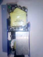
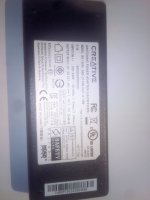
I am trying to repair a small (50ish W) SMPS. I don't believe it matters, but the thing is used to power a set of speakers (that's why I'm posting in Amplifiers, if the moderators have other suggestions, please move the thread to where it would be more apropriate).
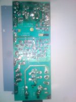
When I first disassembled the power supply, I found that the MOSFET and the current shunt resistor were blown. I replaced those, but to no avail - I could not see anything happening on the primary side. After a bit of poking around with a voltmeter, I came to a realization that the PWM controller is also dead. It's a tiny SOT23-6 package, and it had a couple of letters on it, but Googling gave no result, so I went on to reverse engineer the important parts of the circuit. I came to a conclusion that the supply is of flyback topology, and by pinout and package (and considering local availability), I decided to replace the IC with an NCP1521. The partial schematic I reverse engineered seems almost identical to the suggested schematic in the NCP1251 datasheet.
There was also a small two-transistor circuit that was used (if I am interpreting it correctly) to block the gate drive before Vcc reaches a certain level. Both of those transistors were giving me a dead short, so I just removed them and connected the gate drive pin of the controller to the MOSFET gate.
Success! (Sort of.) I now have correct 27V on the output, the LED comes on (it draws power from the secondary), and it's stable while not loaded. However, if I load the output with 27R (to get 1A out, which should be perfectly fine, since the supply is supposed to be able to put out 1.5A), the output drops down to zero. If I load the output with 4k7, it drops down to 10-15V and begins doing some strange stuff. The controller seems to try to activate, but can't, then goes to some kind of reset state, and then recovers. I am measuring very large ripple on the Vcc pin of the IC, (something like 10VDC + 10Vpp, with no ripple in the unloaded state). The FB pin shows rectangular signals, with period correlating with Vcc ripple and output instability. No respectable current can be drawn from the secondary.
I am aware that the IC I decided to solder in is probably not the same one as the one that originally was there. This was the closest match I could find. I assume symptoms like these might be caused by a faulty regulation loop, but also by the auxiliary winding not being able to provide enough power (voltage?) to take over after the initial pulse. However, I am not brave enough to try and calculate new dividers to power the IC, I would first like to hear ideas from people who might have seen this behavior before.
If any more information is needed, I can provide measurements, photos, partial schematics, o'scope traces, whatever.
Thank you in advance.
Z.
P.S. I know it might be much easier (and perhaps cheaper) to just buy a new power brick and be done with it, but I'm a cheapskate. And I also like tinkering with this stuff, I consider it brain exercise. We all learn from new experiences, and seeing behavior like this is a new one for me.
As a non-professional with not much to contribute, I've spent many hours only reading the forums and learning new and interesting things. Now, the time has come when I am facing a wall and I need advice from people more experienced than myself. Please forgive me if a problem I am facing is not challenging.
I am trying to repair a small (50ish W) SMPS. I don't believe it matters, but the thing is used to power a set of speakers (that's why I'm posting in Amplifiers, if the moderators have other suggestions, please move the thread to where it would be more apropriate).
When I first disassembled the power supply, I found that the MOSFET and the current shunt resistor were blown. I replaced those, but to no avail - I could not see anything happening on the primary side. After a bit of poking around with a voltmeter, I came to a realization that the PWM controller is also dead. It's a tiny SOT23-6 package, and it had a couple of letters on it, but Googling gave no result, so I went on to reverse engineer the important parts of the circuit. I came to a conclusion that the supply is of flyback topology, and by pinout and package (and considering local availability), I decided to replace the IC with an NCP1521. The partial schematic I reverse engineered seems almost identical to the suggested schematic in the NCP1251 datasheet.
There was also a small two-transistor circuit that was used (if I am interpreting it correctly) to block the gate drive before Vcc reaches a certain level. Both of those transistors were giving me a dead short, so I just removed them and connected the gate drive pin of the controller to the MOSFET gate.
Success! (Sort of.) I now have correct 27V on the output, the LED comes on (it draws power from the secondary), and it's stable while not loaded. However, if I load the output with 27R (to get 1A out, which should be perfectly fine, since the supply is supposed to be able to put out 1.5A), the output drops down to zero. If I load the output with 4k7, it drops down to 10-15V and begins doing some strange stuff. The controller seems to try to activate, but can't, then goes to some kind of reset state, and then recovers. I am measuring very large ripple on the Vcc pin of the IC, (something like 10VDC + 10Vpp, with no ripple in the unloaded state). The FB pin shows rectangular signals, with period correlating with Vcc ripple and output instability. No respectable current can be drawn from the secondary.
I am aware that the IC I decided to solder in is probably not the same one as the one that originally was there. This was the closest match I could find. I assume symptoms like these might be caused by a faulty regulation loop, but also by the auxiliary winding not being able to provide enough power (voltage?) to take over after the initial pulse. However, I am not brave enough to try and calculate new dividers to power the IC, I would first like to hear ideas from people who might have seen this behavior before.
If any more information is needed, I can provide measurements, photos, partial schematics, o'scope traces, whatever.
Thank you in advance.
Z.
P.S. I know it might be much easier (and perhaps cheaper) to just buy a new power brick and be done with it, but I'm a cheapskate.
And I also like tinkering with this stuff, I consider it brain exercise. We all learn from new experiences, and seeing behavior like this is a new one for me.