oh man, that's alot of stuff that could go wrong! i can throw out the transformer being the wrong type though. Norazmi has used this transformer with success before and i've found datasheets (if you can even call them that) that specified these were good from 20khz-100khz as power transformers in smps design. At the 50khz i'm running it at, I should be able to get around 350 watts from it...Time to start the debug!
You are using an out of date browser. It may not display this or other websites correctly.
You should upgrade or use an alternative browser.
You should upgrade or use an alternative browser.
12v 250w Car SMPS based off SG3525
- Thread starter codex653
- Start date
DCPreamp
New member
Okay, cool! At least no worries about the transformer. So move on to the 12VDC making sure it is clean and holds up at higher current levels. Remember, even pulling just 100W out of your SMPS requires 10 to 12 Amps at 12VDC! And to pull 350W out of your supply will take almost 40 Amps!
So before worrying about your SMPS working right or not, check your 12V source and maybe add a battery to bolster the current output capability just to be sure. Then we'll move on...
So before worrying about your SMPS working right or not, check your 12V source and maybe add a battery to bolster the current output capability just to be sure. Then we'll move on...
yup that's what i've been taking care of all day today. Well...atleast...my battery has been charging all day. I have one of those ups batteries but it was down to something like 6.12v so it needed to be charged. I unfortunately don't have a dedicated charger so I had to use a transformer/rectifier/filter setup and "regulated" the voltage with a variac. Stays at a stable 13.3v and the the battery voltage has been steadily increasing all day! I'll probably be able to get it all set up for testing tomorrow with the battery in parallel with the transformer/rectifier/filter setup. Hopefully that will give me the extra boost needed.
Just thought i'd mention this as a side note, but i've been using a 1.2KVA variac (connected to a mains transformer primary) to help me get the correct voltage since none of my transformers I have can output a rectified 12vdc with modest current capabilities. The highest current one i had was a 40v 6A transformer. I just turned down the primary voltage in order to lower the secondary voltage, thereby enabling me to achieve 12vdc. Anytime the voltage sagged due to current i just turned the variac up further to compensate for the voltage loss. It was at 14.4v and 7A (yes i know i was pushing the limits of the transformer a little bit...) when everything was freaking out on my circuit, but I can't guarantee that it was a very clean supply. We'll just see how it goes with the battery/trafo combination tomorrow and hopefully there will be better results. What I would love to have is a fully fledged car battery, but this thing hasn't proven to be clear of faults so that probably isn't a good idea just yet
Just thought i'd mention this as a side note, but i've been using a 1.2KVA variac (connected to a mains transformer primary) to help me get the correct voltage since none of my transformers I have can output a rectified 12vdc with modest current capabilities. The highest current one i had was a 40v 6A transformer. I just turned down the primary voltage in order to lower the secondary voltage, thereby enabling me to achieve 12vdc. Anytime the voltage sagged due to current i just turned the variac up further to compensate for the voltage loss. It was at 14.4v and 7A (yes i know i was pushing the limits of the transformer a little bit...) when everything was freaking out on my circuit, but I can't guarantee that it was a very clean supply. We'll just see how it goes with the battery/trafo combination tomorrow and hopefully there will be better results. What I would love to have is a fully fledged car battery, but this thing hasn't proven to be clear of faults so that probably isn't a good idea just yet
DCPreamp
New member
Great progress...
Sounds good! I think you're on the right track. The battery will work great as a monster filter capacitor providing lots of peak current during high-power tests.
Based on the description of your power supply, sounds like a big, powerful, off-line SMPS may be near the top on your project list
Sounds good! I think you're on the right track. The battery will work great as a monster filter capacitor providing lots of peak current during high-power tests.
Based on the description of your power supply, sounds like a big, powerful, off-line SMPS may be near the top on your project list
Based on the description of your power supply, sounds like a big, powerful, off-line SMPS may be near the top on your project list
oh you have no idea!! I already have the circuit schematic and everything for it!! Gonna have to modify it slightly however to get a bunch of different regulated voltages. I am building this one i'm doing now in part to help me get a good base for the design of the more dangerous off-line one. But before I hit the nice 1KW level smps, i'm gonna try for something smaller first. Probably another 250-300 watt one to power my sound system I made for my college dorm room.
oh my goodness!! this high current power supply is becoming a major set back!! ;ww:
Even with the battery in parallel with the initial transformer supply, the voltages still dropped down to around 7v with a 7A load! And then of course the mosfets started to heat rapidly again cause they weren't switching fully because of the too low voltage...aggghhh :"::
I think i'm going to resort to taking the battery out of my car and testing it with that!!! That has MORE than enough current capability! Of course I'm going to install an in-line fuse so that I accidentally don't cause some major battery explosion. I'm thinking 15A sounds good considering I'm having trouble even going past 4A without major issues What do you think
Even with the battery in parallel with the initial transformer supply, the voltages still dropped down to around 7v with a 7A load! And then of course the mosfets started to heat rapidly again cause they weren't switching fully because of the too low voltage...aggghhh :"::
I think i'm going to resort to taking the battery out of my car and testing it with that!!! That has MORE than enough current capability! Of course I'm going to install an in-line fuse so that I accidentally don't cause some major battery explosion. I'm thinking 15A sounds good considering I'm having trouble even going past 4A without major issues
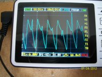
What do you thinkCheck out this waveform I'm getting! Don't freak out just yet...this isn't the actual normal waveform. I've created a video that i am uploading to youtube right now that explains things a bit better and where this waveform comes into play.
Some things I noticed after the video are as such:
1. Snubber resistors are blackening from overheating...no surprise there. Perhaps I need to change the component values so that I don't create a low impedance path at 50Khz. Maybe that could be part of the cause of the freaky waveform? just a thought
2. Gate resistors are starting to show signs of slight discoloration from heat dissipation and the gate drive transistors (BD139 and BD140's) on the driver board are getting slightly warm as well...i'm assuming blackening gate resistors are not exactly normal operation.
3. Transformer did not get hot, yay!
4. Even better, the mosfet heatsink heated up and then stayed at what felt like a constant temperature over the span of 5-10A and did not get near as hot as last time though it was still very warm. This is apparently due to the more stable voltage of the car battery. The voltage never dropped below 12.4v i believe.
5. The frequency stayed at a stable 52Khz the entire time, even during the freaky wave form. At least that's something good
6. I was slightly annoyed when it still refused to work properly ((@ haha
I'll post a link to the video next
Attachments
-
 Crazy Waveform.jpg258.4 KB · Views: 38
Here's the link to the video:
https://www.youtube.com/watch?v=03vFHtmKrYw
pardon the blurriness...I don't exactly have the greatest camera
https://www.youtube.com/watch?v=03vFHtmKrYw
pardon the blurriness...I don't exactly have the greatest camera
DCPreamp
New member
The video was great - it really helped a lot to see your set-up and how you ran the test.
First, I must compliment you again on your SMPS - beautiful work! It looks very professional and clean. Once it's tweaked and running perfectly, you'll be one proud papa!
Now, about your test:
1) Your clip-lead on the 12V side - you need to get rid of the clip lead and use something like 10AWG wire, a heavy-duty fuse and holder, and short wires. Your clip lead alone could be dropping a couple volts causing most of your problems.
2) To sense the primary current, you shouldn't use a resistor unless it is a real current shunt ( http://www.elexp.com/tst_50a.htm ) as they have a resistance of just a few milli-ohms. Or, you should use a clamp-on ammeter or a 20amp-capable DMM (it will have a very low voltage drop at higher current levels.
3) Your R-C snubbers may be too low. It won't hurt anything to raise their values a bit. The only result will be some additional peaks on the Drain waveforms.
4) When taking waveform readings, grounding is ultra-critical! Your scope's ground lead should be either connected to the Source-leg of one of the transistors, or to an additional small wire soldered to the ground of one of the primary filter-caps closest to the FETs. Even moving the ground lead just a few inches will alter the reading.
5) Just as grounding is important, where you pick up the reading is fairly important, but not as critical. You can pick up the Drain waveform from the Drain lead, the transformer primary, or the R-C filter's component connected to the Drain. With proper grounding, you should see an accurate Drain waveform. In theory, to look at the Drain switching waveforms, you should have the scope's ground connected to the Source lead of a switching transistor and the signal lead on the Drain of the same transistor.
6) The clip-leads for hooking up the load resistors is okay. Because of the higher voltage, the current is lower and not as big of an issue. You can also bolt your load resistors down to a metal plate or ideally thermally secured to a heatsink to greatly improve their power handling capability. You will be able to run them longer without damaging them too.
7) Your gate resistors shouldn't be changing color, so something must be going on with them. I would seriously consider running 10ohm 1/4W parts. That's what I use for just about FET driving with excellent results.
So, take the next steps with the heavier wire, the car battery, measuring current, and checking the Drain waveforms. You may be closer than you think. Yep, clip-leads and high-currents don't mix!
1. hmm time to break out the car jumper leads! those are freakin massive.... And i already had a 15A fuse in place as well, you just couldn't see it cause it was behind the battery
2. What's the difference between using the shunt i have now and a proper shunt other than a lower resistance level? The shunt I made was 125 mili-ohms and barely even got warm when under the ten amp load. I have enough resistors where I could lower it down to 10's of mili-ohms if i needed to. The one I have seems to work well enough?
3. I'll look at changing those once I redo the power section again and see if it's still causing some problems after that.
4. A few inches?! oh my goodness! I knew grounding was important but never though a few inches would make a difference at this frequency. I thought "hey ground is ground right?", but guess I was wrong! Thanks for the information! never knew that haha
5. Ok, so basically make sure grounding is good
6. Yah I was trying to figure out how to do that yesterday cause they got so dang hot. I think I'm going to have end up clamping them between two heatsinks.
7. 10 ohm 1/4 watt is exactly what I have It certainly didn't do this before in the previous stages. I wonder what could be causing it??
I'll try and get to the testing today but I'm not sure how far I'll get. Got a busy day ahead of me! Thanks again though for the in depth replies! You've greatly helped me!
2. What's the difference between using the shunt i have now and a proper shunt other than a lower resistance level? The shunt I made was 125 mili-ohms and barely even got warm when under the ten amp load. I have enough resistors where I could lower it down to 10's of mili-ohms if i needed to. The one I have seems to work well enough?
3. I'll look at changing those once I redo the power section again and see if it's still causing some problems after that.
4. A few inches?!
oh my goodness! I knew grounding was important but never though a few inches would make a difference at this frequency. I thought "hey ground is ground right?", but guess I was wrong! Thanks for the information! never knew that haha5. Ok, so basically make sure grounding is good
6. Yah I was trying to figure out how to do that yesterday cause they got so dang hot. I think I'm going to have end up clamping them between two heatsinks.
7. 10 ohm 1/4 watt is exactly what I have
It certainly didn't do this before in the previous stages. I wonder what could be causing it?? I'll try and get to the testing today but I'm not sure how far I'll get. Got a busy day ahead of me! Thanks again though for the in depth replies! You've greatly helped me!
DCPreamp
New member
That's great! You'll have this thing dialed-in in no time! Great work!
I only mentioned a proper shunt because of the temperature-coefficient. A high-end shunt's values don't change with increased temp, but resistors do. With your shunt, you're back to your original problem: Supply voltage is too low. At 10Amps, your 125mOhm shunt is dropping 1.25V! Then your 12V supply is suddenly 10.75 and you're losing a lot of your supply's head-room. Your shunt should be more like 20mOhm - then at 10A, you're only losing 200mV and there's a way better chance your supply will operate normally - even under a heavy load.
Yeah, precise o'scope signal measurement is definitely as much art as it is science. Well, okay, it's all science, but there's a lot to consider and to maximize precision, noise, grounding, and radiated signal all need to be considered. But you're getting all the bugs worked out and making great progress!
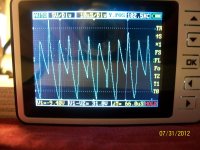
Well I was finally able to test out the switching supply when it was directly tied to the battery through the thick power leads I have soldered directly to my board. I have not gotten the current shunt yet so I don't know exactly how many amps it was drawing, but I used the same power resistors as before to load the output so it should still be the same amperage.
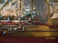
Anyways, when loaded with one 10 ohm resistor, the power supply voltage only went from 12.57 to 12.44 and I ended up getting the waveform shown in the first picture. The second picture shows the ground lead for my scope soldered right next to the power mosfet's source. If you will notice in the waveform picture, the frequency doubled exaclty. Where before it was 51Khz, it is now 102Khz. This is very interesting I think as it's the SG3525's internal frequency, but I don't have the slightest idea what could be causing it?
I feel so close but yet so stinkin far away -)
Attachments
-
 Double Frequency (1).jpg311.2 KB · Views: 53
 -
 ground lead scope.jpg279.8 KB · Views: 77
Other than the "ChongX" electrolytic capacitor, everything looks really good and I compliment you on the build so far :UP: even though it's torturing you... I would be suspicious of low cost electrolytics which crap out at higher ripple currents.
I'm guessing dirty power to the SG3525- can you scope the IC's +V signal? A recent schematic would help troubleshooting.
I'm guessing dirty power to the SG3525- can you scope the IC's +V signal? A recent schematic would help troubleshooting.
“Electrical Engineering, Mechanical Engineering and a minor in Business”
That will be a very fun education. You will be able to build just about anything.
I was writing up a response to your SMPS problems, but of course windows crashed. Lets see how much I can remember.
I will give it to you straight. If you want to be an engineer you need to learn to take the cold hard facts and deal with them without emotion.
Your transformer is the reason your SMPS does not work. Just about everything that could be done wrong was done wrong with it. From the brief description you gave of the second transformer it will probably work. But i would need pictures of its construction to be sure. Home made litz wire does not work. That is your main problem. Also FYI you never twist wires together more than 2 or 3 turns per inch or you will stress the insulation. The frequency you choose is to high and the wire size and number of strands has to be changed. The number of turns you used is wrong also. Furthermore your clever reverse winding does little to nothing to improve the transformer. Under just the right conditions it can help a tiny bit, but remember the help is so small that commercial winding machines are not made with the ability to reverse the winding direction.
There are other things you should be aware of. Your SMPS will be very inefficient. You have no inductor’s in your +- 35vdc output stage. Inductors store energy and release it during a valley in the waveform. They act as regulators, lowering your peak amp draw. With no inductors you will draw about 1.2 amps from the transformer for every amp on your +- 35vdc output.
Also you have no high frequency/high current caps on your output to absorb the high frequency ripple. This will drastically shorten the life of the electrolytic caps.
In one of your posts you asked how the frequency could change from 50 to 100khz. It did not change. Look closely at that picture again. What you think is a halving of the waveform period is nothing more than an extremely distorted waveform that has a deep valley in the middle, looking like the period of the waveform changed.
I have a couple of questions before i can give any advice on how to fix your transformer (assuming you want my advice).
How are you holding the 2 haves of the transformer together.
What are the dimensions of the winding area on your bobbin. Hopefully you have a dial caliper to measure it. I need two numbers, the width of the winding area the wires can fit in and the diameter of the core the wires are wound on. A reading to 3 decimal places would be nice. As in 1.312“ wide and .562“ dia core.
Other wise I am very impressed with your work. Your PCB layout was very well done and construction was excellent as well. Even if you stopped working on this now you have still made something to be proud of.
P.S. If you make another video try not to wave the camera around like a mad man. Focus the camera on what you are trying to show and hold it still for at least 10 seconds on each spot. A walk around of your SMPS holding the camera on all 4 sides and the top in focus for 10 seconds each would have been nice also.
A fun education indeed!!
Quick thing though, before we get started. I'm really not trying to sound rude at all when saying this, but what are your "credentials" in a sense? Meaning like dcpreamp/norazmi have built many switching supplies before and have more experience in getting them to work, or are you and engineer, etc? Again not trying to be rude, I just don't want to blindly take everything that is given to me in case this is just a teenager advice who doesn't quite know everything. But you do sound like you know at least a LITTLE hahah
Now for some of my own questions and to answer yours:
-Brief description? No pictures? I had I think 5 pictures with descriptions of everything i did to my latest version of the transformer a couple pages back or so.
-Why would homemade litz wire not work? Plenty of people have done it before with no problems
- Yahhhh, I think I had turned it just a 'tad' more than 2 or 3 turns per inch...whoops ((@
-Are you saying the frequency is too high for the transformer or for the litz wire? I'm assuming you mean the litz wire cause I've heard that for it to be very efficient at a certain frequency, wire gauge and number of strands are important. I was just using wire I had on hand at the moment since I really didn't need a 20lb roll of a high gauge wire for $50 when i'm only winding a single transformer...kinda wasteful of money to not see if the stuff I had already worked.
-Number of turns are wrong how? Primary side is wrong? Secondary? Can't get too much variation on turns with the primary....mind telling me why it's wrong and how I can go about correcting it properly?
-Ahhh I wasn't using the reverse winding thing to help efficiency at all...no it was to help get the windings flatter so I could fit more in the window area! By far the flattest windings I've done to date with this method.
-Hmmm yes I probably should add an inductor to the output.
-Eh I'm not too worried about the life of the capacitors for this project. It's turning out to be more of a learning experience project rather than a long term abusive use project, so it just needs to last long enough for me to get it working and then I'll make a quality one that can be constantly used for a long time.
-Ahh ok that would make sense about the frequency thing. Devious little waveform
-Transformer halves are held together with electrical tape wrapped around the sides very tightly....I know i'm gonna get some hate comments on this one, but I couldn't find the clip pins for the transformer! I figured since the two halves magnetically clamp themselves together, electrical tape would provide a decent force to keep them where they are at. It's worked well so far!
-errr...don't have a caliper :/ however I might be able to find the dimensions online??
-I'm not gonna stop working on it! I'm a bit of a perfectionist so if something isn't going right i'm sure gonna fix it! May take a while, but it'll get done
-hahaha sorry about that video I'll try to calm down my "madness" next time
Quick thing though, before we get started. I'm really not trying to sound rude at all when saying this, but what are your "credentials" in a sense? Meaning like dcpreamp/norazmi have built many switching supplies before and have more experience in getting them to work, or are you and engineer, etc? Again not trying to be rude, I just don't want to blindly take everything that is given to me in case this is just a teenager advice who doesn't quite know everything. But you do sound like you know at least a LITTLE hahah
Now for some of my own questions and to answer yours:
-Brief description? No pictures? I had I think 5 pictures with descriptions of everything i did to my latest version of the transformer a couple pages back or so.
-Why would homemade litz wire not work? Plenty of people have done it before with no problems
- Yahhhh, I think I had turned it just a 'tad' more than 2 or 3 turns per inch...whoops ((@
-Are you saying the frequency is too high for the transformer or for the litz wire? I'm assuming you mean the litz wire cause I've heard that for it to be very efficient at a certain frequency, wire gauge and number of strands are important. I was just using wire I had on hand at the moment since I really didn't need a 20lb roll of a high gauge wire for $50 when i'm only winding a single transformer...kinda wasteful of money to not see if the stuff I had already worked.
-Number of turns are wrong how? Primary side is wrong? Secondary? Can't get too much variation on turns with the primary....mind telling me why it's wrong and how I can go about correcting it properly?
-Ahhh I wasn't using the reverse winding thing to help efficiency at all...no it was to help get the windings flatter so I could fit more in the window area! By far the flattest windings I've done to date with this method.
-Hmmm yes I probably should add an inductor to the output.
-Eh I'm not too worried about the life of the capacitors for this project. It's turning out to be more of a learning experience project rather than a long term abusive use project, so it just needs to last long enough for me to get it working and then I'll make a quality one that can be constantly used for a long time.
-Ahh ok that would make sense about the frequency thing. Devious little waveform
-Transformer halves are held together with electrical tape wrapped around the sides very tightly....I know i'm gonna get some hate comments on this one, but I couldn't find the clip pins for the transformer! I figured since the two halves magnetically clamp themselves together, electrical tape would provide a decent force to keep them where they are at. It's worked well so far!
-errr...don't have a caliper :/ however I might be able to find the dimensions online??
-I'm not gonna stop working on it! I'm a bit of a perfectionist so if something isn't going right i'm sure gonna fix it! May take a while, but it'll get done
-hahaha sorry about that video
I'll try to calm down my "madness" next timeSorry about the long delay, windows was crashing everyday, so i re-formated and reloaded.
“Quick thing though, before we get started. I'm really not trying to sound rude at all when saying this, but what are your "credentials" in a sense? Meaning like dcpreamp/norazmi have built many switching supplies before and have more experience in getting them to work, or are you and engineer, etc? Again not trying to be rude, I just don't want to blindly take everything that is given to me in case this is just a teenager advice who doesn't quite know everything. But you do sound like you know at least a LITTLE hahah”
Fair question, but lets do it this way. Read what i have to say with the eyes of a skeptic and you tell me if i am some jerk off kid.
BTW i like dcpreamp to, if i needed electronic advice for the smps i would welcome his help. That Canadian guy was helpful to.
“-Brief description? No pictures? I had I think 5 pictures with descriptions of everything i did to my latest version of the transformer a couple pages back or so.”
I think you misunderstood me, you only provided information on the transformer you are currently using. Thats how i know it will never work. The other transformer you made, all you said was you wound it in a more conventional manner. That one will probably work much better, but if you used the same amount of strands of wire it will have problems with heavy loads.
“-Why would homemade litz wire not work? Plenty of people have done it before with no problems”
No, actually they have not. I know you have been told it works, but it does not. After reading thousands of posts, i can tell you that many people claim there smps works because they get something out of it. But if pushed to measure performance they are lacking.
“-Are you saying the frequency is too high for the transformer or for the litz wire? I'm assuming you mean the litz wire cause I've heard that for it to be very efficient at a certain frequency, wire gauge and number of strands are important. I was just using wire I had on hand at the moment since I really didn't need a 20lb roll of a high gauge wire for $50 when i'm only winding a single transformer...kinda wasteful of money to not see if the stuff I had already worked.”
I will explain more later, but the frequency was to high for the way this should have been designed and i will give you links for cheap wire.
“-Number of turns are wrong how? Primary side is wrong? Secondary? Can't get too much variation on turns with the primary....mind telling me why it's wrong and how I can go about correcting it properly?”
I will go in to this in depth later, but considering your choice of primary turns was based on how many times the rooster crowed at midnight. And the secondary was determined experimentally i think there is some room for improvement in your method.
“-Hmmm yes I probably should add an inductor to the output.”
I would say after you have the transformer fixed and running and get some data then add some inductors and see if you can measure the improvement.
“-Eh I'm not too worried about the life of the capacitors for this project. It's turning out to be more of a learning experience project rather than a long term abusive use project, so it just needs to last long enough for me to get it working and then I'll make a quality one that can be constantly used for a long time.”
That is a valid reason for not adding high freq/high current caps. As long as you are not lying to yourself or making lame excuses like i it will be ok, you are staying in the real world and moving ahead.
“-Transformer halves are held together with electrical tape wrapped around the sides very tightly....I know i'm gonna get some hate comments on this one, but I couldn't find the clip pins for the transformer! I figured since the two halves magnetically clamp themselves together, electrical tape would provide a decent force to keep them where they are at. It's worked well so far!”
I do not see a problem with electrical tape since this smps has just been made to learn and gather data on. Going from memory you need about 5 lbs of clamping pressure on the 2 halves and your elastic electrical tape is probably working fine. I have also read that tie wraps can be used but i find it hard to believe that they hold up to long term temperature affects.
“-errr...don't have a caliper :/ however I might be able to find the dimensions online??”
$7 free shipping.
http://www.ebay.com/itm/Trademark-T...463?pt=LH_DefaultDomain_0&hash=item43afd58767
I already looked online Amidon has no specs.
“-I'm not gonna stop working on it! I'm a bit of a perfectionist so if something isn't going right i'm sure gonna fix it! May take a while, but it'll get done”
I can see you take pride in your work.
I will post this first part so you do not think i forgot about you and start typing up the rest.