Silvio
Well-known member
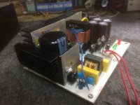
Audio smps 550 watts 700watts peak
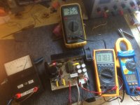
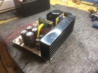
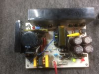
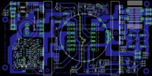
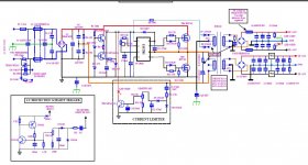
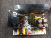
Here is an audio half bridge smps that can be altered in quite a lot of ways. This smps was designed in such a way that different drivers can be adopted, also that different protection circuits can be adopted. The one presented here is with a current limiter which works very well.
The driver choice at the moment is with the IR2153 which is rather cheap. However other options can be made to be driven with an SG3525 and can be regulated. Options for feed back can be included on a small pcb having an opto coupler and Zener to stabilize the output voltage. Provisions have been made for output inductors. However these are made very small (5uH) at the moment as this smps is intended for audio purposes and not stabilized, the IR2153 works at full duty cycle and not much noise is generated.
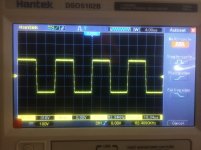
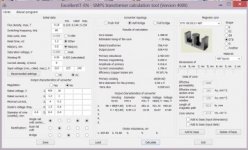
The transformer construction is very important and tight coupling was kept in mind during winding. However the input and output snubbers where not needed as the wave forms came out very clean and free of distortion and spikes. A video is available on youtube regarding the construction of the transformer which can be found on this link. https://www.youtube.com/watch?v=_K3ixhcTYFg Here the whole construction of the trafo is seen with some very good tips for good transformer construction for this smps.
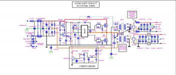
Circuit description
As the smps is switched on the rectified DC voltage starts charging the main bulk capacitor limiting the current through the 15 ohm NTC thermistor. As the voltage at the bulk cap reaches around 170 vdc TR1 and 2 are coupled in a constant current source which the voltage at TR1 is clamped at 160v via ZD1. TR 2 is clamped at 10 volts via ZD2. together they start charging C8 when the threshold voltage of around 9.2 volts. The chip starts oscillation The auxiliary supply takes over and stabilize the voltage at the pin 1 of the IR2153 at 13 volts via ZD3 hence the constant current source is switched off. At the same time it starts charging the main secondary caps the current however is limited by the current limiter to around 6 amp on the input of the drain of TR4 and TR5. A 2 turn loop at the transformer supplies the gate of the triac at the input shorting out the NTC thermistor and full power is now available. All this happens in the blink of an eye.
Short circuit and current limiting.
The choice of current limiter was chosen however I admit its not my design and after a few trimmings in the coupling capacitor and also in the some resistor values from the original circuit works very nicely. It limits the output power to 700 watts of which this can also be adjusted for higher and lower power. This will protect both amplifier and the smps itself during over load by reducing the output voltage and the output current drops to around 2.5 amps until the overload is removed.
The current sensing can be done either with a current transformer or with a more simple method which I chose. In my case the current sense is done by sensing the ripple voltage at the center point of the fets. When the threshold is reached TR3 pulls down the supply at pin 1 via Led 1 of the IR2153 and thus switching it off. A point is reached where the load reduces and also the ripple hence and oscillation starts again. This action is repeated until reasonable load is reached and normal operation starts again. If a dead short is present the output current is limited to 2.5 amps. >>>>> Continues in pdf
Attachments
Last edited:

