Drive signal issues with half bridge

I've been able to get the diodes but only BY396 Available 70V Rms Max Vfd Max Ifd 3A Switvhing time 150NS i will test them. The other option is BY399 same specs 100V Vfd but a switching time of 400NSec that's bad. For the output caps i got space on my board for 2X470uF 50V per rail. The only issue i have left is to get the data for the yellow mpp toroid core i will use for my forward mode inductor.
 
Last edited:
I've built a fullwave recitifier bridge with BY396 followed by 2X 9 turns on the MPP core bifilar and 2X270uF 50V on each rail. Am currently doing testing. Up to now i have loaded the output with 47R resistor and am getting +5.5V and -4.5V respectively. I will do some more testing and post back. There is ~1V drop across the inductor all the above figures were obtaine dby loading the SMPS with ~44V ac. I will try 109Vac next
 
Tested with 109Vac got +12.7V and -13.1 V with 47R load on each output. I left the unti running for 10mins nothing heated up. I will do some lengthier load testing tomorrow
 

MicrosiM

Administrator
Staff member
Tested with 109Vac got +12.7V and -13.1 V with 47R load on each output. I left the unti running for 10mins nothing heated up. I will do some lengthier load testing tomorrow

Thats a good start!

then

109VAC input, you got +- 13VDC =26VDC in total, right?

You can make voltage doubler test i think!
 
Hi Microsim thanks for reply and sorry for long reply as well. I just tested it a few minutes ago loaded with 100W bulbs on each output and properly connected. This time i got exactly +-13V on each output (not like +13.1 and -12.7 like last time) loaded with 109Vac and yes thats 26V DC at output in total. The bulbs started to heat up got warm(not glowing due to the low voltage) and the mosfet heatsink got very slightly warm nothing burnt or overheated. I have switched it off and will run it again for some 30 mins or so.
If you are ok with the above and after i post back after the 30 mins test, i will connect my transformers to get approximately 220V (sorry no voltage doubler switch built in this psu) with another 2X100W bulbs but this time in series with the live input and keep the other 100W bulbs on each output.

By the way i got my 10X IR2153 yesterday and i also 10X SG3525A and 10X IR2110 plus my long awaited inductance/capacitance meter. I will try to measure the leakage inductance of the main transformer after the 30 mins test and post it here. Ok the test begins...... NOW!
 
ok i've tested the unit for 1 hour on 109V ac intial voltage was +-13.2V when lamps were cold and was at +-13.6V exactly when lamps got warm. The mosfet heatsink are very slightly warm as before and the trasnformer is dead cold. Am going for the 220V isolated test as mentionned above and post back. Hope the mosfets don't fry again like my lst test
 
Higher Voltage test

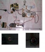
Hi Microsim, i did the isolated high voltage test i got 210Vac with my transformers wired. Nothing blew up and the bulb in series with the SMPS remained off. Output voltage with the unit loaded with 100W bulbs was +-25.9 volts. The test setup can be seen here as well as how the bulbs on the output were glowing:Test results.jpg. I left the unit on for around 5mins and after switch off i checked for heated componets. Transformer, input and output diodes, forward inductor did not heat up at all, but the mosfet heatsink got really hot i was unable to touch the heatsink for more than 2-3 seconds (sorry no temperature probe on my meters for the time being but planning to get one with temperature measurement). I wait for your reply on how to proceed next and what to do next. As i get some time, i will measure the leakage inductance for the main transfo with all secondaries shorted.
 

MicrosiM

Administrator
Staff member
OK

It looks to me that you made a new setup, witch is good.

I would like to see waves ACROSS G+S of mosfet and D+S of mosfet. show me waves with SMPS loaded and Not loaded, both cases

Value of capacitor in series with the transformer?

Output current and voltage while the SMPS is loaded? and without load?

Heatsink you are using is too small
 
Hi Microsim, i will make the measurements you have requested and post back. For output i can measure the DC output voltage unloaded and the dc op voltage and current when loaded and same for the mosfet. I will do the testings at 109Vac for safety reasons The value of the Series capacitor with the main transformer is 2.2 uF. Do you really think the heatsink is too small for a 140W (+35V 2A and -35V 2A) SMPS? I can add a fan its not an issue.
 
Last edited:

MicrosiM

Administrator
Staff member
Try to change the capacitor from 2.2uF to 1uf and see if mosfet heat less

mosfet you are using?
 
Hi Microsim, thanks for replying. I am starting the test. My mosfets are IRF840. I have attached the latest schematicsSchematics.jpg. I will do the test you have mentionned for the waves and then change that capacitor and see what happends.
 

MicrosiM

Administrator
Staff member
Hi Microsim, thanks for replying. I am starting the test. My mosfets are IRF840. I have attached the latest schematicsView attachment 1110. I will do the test you have mentionned for the waves and then change that capacitor and see what happends.


Try to add:-

1- resistors 10R from each output of TL to B of each drive transistors, 1 resistor for each pair.
2- You need a capacitor 1uF in series with the GDT Primary, or a 10R resistor
 
Amendments

Hi Microsim I did the test at lest for the voltage and current part. For 109 Vac and output loaded with 1k resistor i got 14.47V and 14.7mA per output. Loaded with 100W bulbs i got 13.75V and 117mA. I got tempted to test the voltage and current at 210Vac isolated. I got 0.15A but at second switch on to measure the voltage the unit stopped working no smoke or bang. My mosfet are shorted GDS as well as my output diodes.I prefer it failed with my meters than with my scope connected it was obvious this would happend given the temperature at which the mosfets were running at 210Vac. I am currently replacing the failed components and will implement the changes you have requested.
The schematics has been amended as follows:Schematics updated.JPG
 
I have just replaced the components only the Mosfets have shorted GDS. the dioes are intact I have added 1 uF in series with GDT primary. I did not have 10R but 100R resistors handy for base resistors for the totem poles. I will test the oscillator section and POwer section again starting at 12Vac, 60Vac and see how things run.
 

MicrosiM

Administrator
Staff member
It will be impossible to know the problem without showing scope waves.


I wonder why mosfets are blowing
 
Hi Microsim just seeing your post. I have replaced mosfets and implemented the circuit above except with 100R base resistors. I made a quick check at the waveforms and all went ok at 12Vac and 40Vac but the low side mosfet died at 109Vac loaded with bulbs. I will replace the dead low side mosfet and test and 12 and 40Vac stop there and post the measured waveforms. I will also recheck the wiring.
 
Back to square one 12Vac loaded measurements

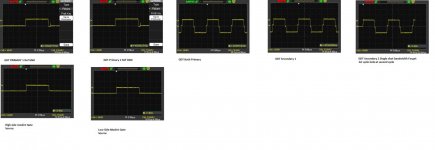
Hi Microsim please find attached measurements for only the oscillator:unloaded measurements.jpg and the whole system with 12Vac applied and 1K load on each output:Smps loaded 12Vac.jpg and the latest schematics:Schematics 3.jpg.

There seems to be no issue at this voltage i await your comments before goign to test it at 40Vac
 
Last edited:

MicrosiM

Administrator
Staff member
Waves across GS looks completely square, and looks smaller.

Change GS resistors to 10K each
Change G resistors to 10R each


D2 and D5 put a resistor in parallel of each diode 10R


Waves really looks strange at GS directly, all other waves looks GOOD and NORMAL.
 
Test with new circuit

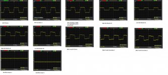
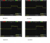
Hi Microsim please find attached the latest measurements 12-Jun-11.jpg but i have had issues with the following implementation:Capture.jpg I had to remove R17 and R18 out of the circuit. They would heat the Totem pole and reduce the primary square wave to +-5V and make the GDT buzz at times. I am thinking if its not the GS resistors (initially 1K)which are making the mosfet heat up and most probably blow due to interaction with Q5 and Q6 when they try to switch off the mosfet? I await for your reply.
 
Top