EI-33 based half bridge

Hi Microsim thanks for the reply i will try to lower the Cb (series cap) i just went with a 1uF cap i will calculate it properly and implement it and see what it turns out to be. If it turns out wrong i will try the 2uH you mentionned, is it basically an air cored coil? thanks
 
Cap did not prove useful

Hi Microsim this is the current waveform with the series cap reduced to 330nF :ISHI.jpg did not prove useful. Could you please tell me more about the inductance you were sepaking of? mainly what kind of former are you suggestingh please thanks
 
Hi Microsim the leakage inductance is 10uH sorry i completely forgot the correct range from the time i was working on the other half bridge.
 

MicrosiM

Administrator
Staff member
Hi Microsim the leakage inductance is 10uH sorry i completely forgot the correct range from the time i was working on the other half bridge.

that 10uH is too much I think, make sure your measurements are correct.

1~3 uH should be OK
 
REcoiled transformer

Hi microsim sorry for late reply i have recoiled the transformer and obtained a leakage inductance of 4uH this is the current waveform as the SMPS is loaded at 110V:Isense.jpg. It gradually gets worse as i load the SMPS

I did a rough estimate to set the Bmax at 1200G for the EI-33 since information about it is so scarce on the net. Currently i has 38 turns split into two on primary for a switching freq of 70Khz a Bmax of 1200G and area of 1.2 cm sq.

Any help on how i can solve my problem? Add more turns or reduce number of turns?

Thanks
 
PIcs requestted

Hi Microsim this is the pic of the EI-33:EI-33 pic.jpg
I did modify the turns from 38 to 24 and this is what i could get closest to the required half bridge waveform curent I47OHM.jpg. the wave form is taken from a current sense transformer in series with the EI-33 primary
 
Waves across series caps

Hi autoclass A there are the waves across my seies caps(330nF) and the SMPS is powered with 110Vac isolated : cb waves.jpg
 

MicrosiM

Administrator
Staff member
Make sure that D+S waves of your Mosfets are good, and test with 220VAC, then show waves again.

Test with lamp in series.
 

MicrosiM

Administrator
Staff member
Another SMPS

Zeus

This maybe of interest to you!

Another simple SMPS, Hope it will help you
 

Attachments

  • SMPS_2.JPG
    SMPS_2.JPG
    93.2 KB · Views: 284
Hi sorry am back after a veryyy long time been very busy with work. I did a quick test to see if anything would blow up at 220V isolated + bulb and a meter on one output. It did not blow up but voltage stabilized at 32-35V but jumped to 130V and the transformer started buzzing for a small period and then stopped and repeated again. Sorry i don't have any oscillograms to show. I suspect it could be the drive scheme i will give it a test at low voltage and see if it occurs again.
 
Good news the smps survived straight 220V test with a 100W bulb in series. The SMPS was loaded with 100W bulb on each output.

However the bulb in series with 220V did glow for two second very mildly before the smps would start i think its due to my start up time being too long(47K and 47uF statup for TL494) and i know how to reduce it based on my previous SMPS(47K and 10uF).

The EI-33 has been recoiled with 2X18 turns primary and 2X6 turns secondary to give +-25V +-2A (i changed my initial target and i want this SMPS to power an amp) and auxilary is 3 turns to power the ic

The buzzing problem i mentionned was due to the fact that i had reduced primary turns to 2X10.

Current waveform looks better i will need to recoil the current sense transfo, I used it straight from a pc smps and the number of turns it has is too huge from the inductance i measured. It could also have played its parts in giving bad current waveforms but am not sure.

The auxiliary is not powering the ic yet i need to get the SMPS working fine before embarking on the ic bias scheme and completely remove the bench psu powering the ic.


Thats it i'll post more updates and waveforms as i get moving
 
Last edited:
More updates i have recoiled properly my main transformer after some more testing. Its now properly recoiled with 2x13 turns primary and 2 x 5 turns secondary and 3 turns for my auxiliary. Tested it with my previous working TL494 SMPS waveforms are good. The issue i was getting was that the GDT was saturating and i was getting two square waves combined together as much as i can describe it on the primary transfo which was doubling the output voltage.

The GDT is being rebuilt right now
 
EI-33 SMPS Working at mains and survived horrors!

Solved the GDT problem for those it might help: In case you have a GDT with an AL very close to 3000 solution is to combine two similar cores together tape + dip paint to get solid bond. Then wind the GDT. That applies as long as you are using toiroidal cores.

Now another thing with testing with lamps this can be very very very unstable unless the lamps are equalized with very high value resistors(Like the input caps in half bridge) i got the following situation:

Connected 2X100W bulbs in parallel on each output and around 1 metre wire to SMPS.

When testing on isolation transformer at 230V everything went fine each output was at 29V 350mA

When testing with 230Vac live and only 1X100W bulbs on each output all was ok even with meters connected.

When testing with 230Vac and 2x100W bulbs on each output the SMPS was buzzing irregularly(no meters at this point). I checked GDT waveforms, EI-33 primary everything showed normal waveforms. When i connected my ammeter those bulbs thing were pulling 9-10 AMPS! Ammeter was reversed connected and it was connected back to proper polarity guess what reading was fluctuating between 4-6 AMPS!


Added voltmeter on supply rail and everything came back to normal 30V 350mA. My guess is that the shunt resistor in the voltmeter was equalizing current somewhere in my circuit. I have removed the voltmeter and the same problem occured. I think lamps should be bypassed with say 470K - 1Meg resistors for testing since their resistance fluctutates so much with heat. I also found a loose ground connection which was also particiapting in the problem.


But otherwise the SMPS even survived those 10A bursts without burning mosfets but its not a miracle its thanks to the series caps which was properly sized and the overcurrent protection.

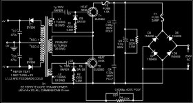
I'll post the final schematic soon. Yes !!! at last a working EI-33 SMPS at diy smps :) it was time!

Next step is going back at lower voltage and implementing the SMPS bias startup scheme and completely remove those auxiliary transformers and power the SMPS Ic from the main EI-33 transformer like proper designs
 
Last edited:
Top