Low Power 240V AC SMPS <30W flyback or forward?

MicrosiM

Administrator
Staff member
Hey Zeus,

Do you have the final schematics and calculations for this project?


Regards
 
Hi sorry for such a lonnnnnnnngggggggggggggg time not being here. I am busy finishing furniture for my new house thats why i wasn't around here for so long, busy with woodworking. But in the little time i had i have investigated further into this flyback psu and why it did not work. I don't recall which ic i was using but investigating futher for flyback an uc3844 or uc3845 is the choice to go for. they are both limited to 50% duty cycle. The only difference between them is the supply voltage UC3845 can work on lower supplies.
I am working with UC3844 now more exactly a TL3844 to be precise i fell on some counterfeited 3844 for cheap and went for the TL3844.

Next the problem i was getting. From my previous current waveforms it seemed that the SMPS was working at Continuous Conduction mode which is more for Dc-Dc flyback. I had to switch to discontinuous conduction mode. There was not enough deadtime in the ic and the magnetic force build up in the core was remaining and at the next conduction cycle it was adding to the field generated which drove my core into saturation at 60Vac with spikes getting as high as 400V dc on the mosfet Vds. what i've done is reduce the duty cycle from 48% to around 30% by increasing the timing capacitor and adjusting the timing resistor.

Second part of the problem is the gap. The E cores i was using were ungapped but Marty brown gives the equation to calculate the gap size. I will not be grinding the centre leg but rather but some paper in between the legs to get the required gap size.
The only issue is that I am not sure about if my logic is correct is once the gap is created automatically the AL will diminish heavily. To me it would seem correct to calculate the transformer turns based on the new AL created with the gap but if someone could confirm that my logic is correct it would save me a lot of time.

I also went into learning what gapped cores really are i.e. the core materials is mixed with additional particles that create small distributed gaps in the core. the core looks like a normal core there is not cut or hole or space. i was confused on that. But a gapped core has a significantly lower AL that an ungapped core. I was lucky to get a damaged laptop pack, cracked it open and took the core out. When measuring the AL i got the following measurements:

FLyback core with gap in material AL:583nh/N2 compared to an EI33 ungapped core from a half bridge pc power supply AL is:3510nH/N2. Thats a huge difference.

i have rebuilt the whole circuit on i have to rewind the core. I will create the core gap, measure the new AL and wind the transformer and run the whole thing at 30% duty cycle and 70KHz switching to see what happends. I will wind a transformer based on the gapped core and create another one based on my "paper gapped" core.

Another thing is that creating core gaps for flyback using paper requires gaps in the range of millimetres to be built. Without a micrometer screw gauge it is very difficult to get it accurate. Micrometers are rare and expensive here so i used a vernier caliper instead. but to get the number of paper sheets i need for my gap i have had to measure the thickness of 70 sheets, then divide it by 70 to get the thckness of 1 paper sheet. from 1 paper sheet thickness i equate with my gap size to get the number of paper sheets needed.

Just a word for you amplifier builders reading this thread, from a core efficiency perspective flyback SMPS won't get you as much power from a core as a half bridge will do but it has its applications and the circuit is simpler. The core however as you have read up is more complex (but not imposible) to build compared to a half bridge design. E.g an EI33 core can give you only 40-50W in flyback mode but 150-170W in a half bridge application. But you have only 1 mosfet and no transformer/ic gate drive issue. flybacks are more appropriate for low power which i am aiming at.


Any helpful comments are welcome as usual

P:S: Great job for the new site microsim it looks really great.
 

KX36

New member
I'm a bit late to chime in on this project, but you'll typically need at least an 800-1000V FET for the full 10% tolerance of 240V mains for flyback, single switch forward or push-pull. e.g. in flyback, there's the rectified input voltage plus the reflected output voltage plus a spike from leakage inductance. You can limit the spike with a voltage clamp, but not the rest. It depends how you design the flyback. Common practice is to desigh for a 50% duty cycle and use the turns ratio to convert the voltage, and if you do that, the reflected voltage will be twice the input voltage, so potentially 265*2^0.5=375V for the input voltage, multiplied by 2=750V plus the inductive spike. You can see that in the worst case high input voltage even an 800V FET won't be enough.

The good thing about the flyback converter is you don't have to work at the 50% duty cycle enen though it's common to do so. If you increase Ns/Np, you reduce the duty cycle for a given voltage, and reduce the reflected voltage which might help you use a lower voltage FET.

Forward converters with a reset winding can similarly be adjusted by adjusting the ratio of Np/Nr.

30W is possibly a bit much for a DCM flyback, but still doable, possibly with some relatively high peak currents.
 
Hi KX thanks for the reply. I went for flyback due to its popularity and information availability. I am slowly solving the issues i went through and will consider your advice up for the switching FET and increasing NS/NP to to operate at a lower duty cycle.

The power has actually been revised from 30W to around 10W. The controller for the time being will remain UC3845 + the stf11nm80. While waiting for the mosfets to be shipped i will use some irf830 with lower input voltage to the supply while testing.

A question i have is regarding the core. For 10W output power DCM, you would choose a core with how much AL in nH/N2 for the job (This excludes the AL it will drop to after the gap is added to the core)?

I will post my calculations as well soon. Thanks
 

blasphemy000

New member
If you're power requirement is only 10W or so, you might want to look into the TNY2* series of ICs. These ICs have the FET and all of the switching components built directly into the IC. They can be powered directly from the 230VAC line and the voltage feedback network is super easy to setup.

The TNY266 will support up to 10W inside a power adapter or up to 15W in an open-frame design. The higher model numbers TNY267/268 will handle even more power with the 268 handling up to 23W in an open frame design. The solder pads for the IC must be quite large to dissipate heat from the internal FET inside the IC.

There is also the TNY27* series. The TNY276 will handle 10W in an adapter case and 15W in open-frame. These TNY27* series goes all the way up to the TNY280 which will handle 20W inside an adapter and 36.5W in an open-frame design. Again the solder pads must be large to dissipate the heat from the IC, although you could use thermal-glue to attach a small heat-sink to the IC. These can also be powered directly from the mains.

Here is a thread about the small power supply I built using one of these chips. The schematics and board layout are attached in that thread along with a couple pictures of the finished supply. If I would have used a larger switching transformer I could get much more power from this setup, but I wanted to keep the board very compact and I didn't really need more than 5W(7.5W Peak). The TNY27* series switch at an AVERAGE of 132KHz. Here is the datasheet for the TNY27* series of ICs. Also, I'm using a zener diode as voltage feedback in my circuit. Using a 15V Zener will yield around 16.2v due to the 1.2V forward voltage of the opto-coupler. For a more precise control of the output voltage you could use a TL431 programmable shunt regulator with a Trimmer-POT to make the output voltage adjustable(within reason based on your Np/Ns).
 

KX36

New member
The TOP221-227 family is a very similar low parts count flyback IC in a TO-220 3 pin package with integrated FET (from the same manufacturer and closely related to the TNY274-280 mentioned above). Using such parts can be quite restrictive and they may perform poorly (e.g. poor transient response, high noise) or exhibit unexpected behaviour depending on how they work internally (e.g. variable frequency or firing off in bursts at light load etc.) I got some from the 5V aux section of an ATX power supply.


The trick with gapped cores is that magnetic flux takes the path of least reluctance, and just as the current in a series of resistors is basically defined by the largest resistor, flux in a transformer is basically defined by the largest relutance i.e. the gap. What I'm saying is that the gap defines the transformer and the core permeability (or ungapped AL) doesn't really come into the equation. You might select a core based on the loss curves, or you might just pick the cheapest ferrite that is designed to work at your frequency of interest, because it's still going to have negligable reluctance compared to the gap. More imporant is to pick a core which just snugly fits your windings so as to minimise leakage inductance which involves a bit of trial and error. I don't have the equations for the gap at hand but from what I remember it's a relatively simple process to calculate it.

I wouldn't tend to use datasheet AL values when designing transformers, not all manufacturers give you one and IIRC they make assumptions about your design. I use the core geometries, relative permeability and core loss characteristics from the material datasheet. Not that using AL values given is not a valid method, I just don't do it enough to give advice off the top of my head, whereas I know the equation for minimum number of turns for a given flux density and inductance for a given number of turns.
 
Last edited:
Hi thanks to both of you for the replies. The TOP ic's are on my watch list but I still prefer stick to my UC3845 and stf11nm80 due to ease of component replacement in case something burns. I am still curious and will hunt your tny smps around. I did some simulations and effectively found a way to reduce the voltage stress by limiting DTC and using NS/NP ratio to lower the stress voltage seen by the mosfet. My question about the core AL is fully answered thanks KX. I am waiting for components to arrive to move forward. I'll post my simulation results here. I don't know if its a good idea to limit DTC to around 35% to reach my target but let me put everything here and well see forward
 
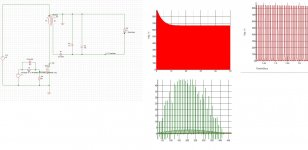
Simulation results

Simulation.jpg this is the simulation result at 100KHz 0.5 DTC any feedback is welcome. the transformer is coiled I need to measure it and set its gap appropriately and the UC3845 controller is working fine. I will assemble the transformer on the board and keep posted. I am planning to run the module to max 110V ac if I manage to get there and nothing blows up. Transformer optimization and high VDs mosfet for 220V will follow afterwards and most probabily some dtc limiting to lower the VDS voltage to a reasonable value
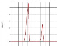
 
Found my issue

After building a core quickly to reproduce the issues I was getting initially I finally found the culprit. Its the leakage inductance that was too high. Attached is a simulated VDS that looks exactly like my scope measurement I will rewind the transformer properly. In case this can help someone who encounters the same issue am glad to help. The transformer voltage will show an inverse of this wave form. the voltage magnitude is highly exaggerated here but I ended up getting nearly a 200V(dc) peak just by feeding 22V ac into the circuit Capture.JPG.
 
Better results but still

Hi am back after a long time and I wanted to get back to this project given that I got better cores to work with. I started with a simple DC flyback working from 18V to get 5V to get something simple working first and iron out all the issues. I can post more details if needed. Attached are my waves My question is my core saturating currently given the bump I highlighted in my IDS or is that another issue? flyback current issue.jpg .The core is an EE2511 and the Bmax was set to 300G. I feel I am using a too high magnetizing force or my leakage inductance could be too high but i'll let the comments come in, anyways I will have to rebuild that transfo anyway given the issue. the aim here is once I iron out the issues at low voltage I will then move to build a transformer for 220Vac.

The leakage inductance is 15uH and primary inductance 136uH. I know the leakage inductance is high and should be reduced by ten but some info on the current issue I am having would be helpful while am learning to make this work. thanks
 
Last edited:
Got the circuit to work after scoping the circuit. The problem was the mosfet gate resistor which was too high once set properly the current switch off issue got solved. I'll now think of next step and keep posted, but I have something at the back of my mind...why not use a 12V transformer, feed it to an SG3525 and 2 push pull mosfter and feed the mosfet to another 12V transformer to get 220V isolated. the voltage could be increased lowered by changing the duty cycle. That could make the 220V flyback safer to test. Next question is use 50Hz or 50KHz switching for the final transformer..... size v/s time.... I'll have to see if you are thinking variac problem is I got the parts around and i'll barely use it a few times in a year.
 

Jagd.Panther

New member
If you need compact high voltage DC power supply and you want it to be galvanically isolated fomr the mains I'd simply take two similar ATX power supplies, gut one power supply, take a trafo out and then connect secondaries of the both trafo's together.

You don't even need to modify anything on the first power supply (assuming you don't need regulation and you aren't going to draw hundreds of watts)
 
Hi I already did that with 50Hz transformer but you won't get a variable voltage. A small test I made shows that my concept seems to be working nice with SG3525. Next test is a higher 50Hz power transformer and check the waveforms. Its going really fast with 50Hz transformers. I am basically building an inverter except instead of feeding with a battery I am powering it off ac mains and using PWM to control the output voltage. There are 2 other possibilities left which seem interesting, build a half bridge/full bridge smps and the rectify the output to get 100-320V DC by changing DTC. Another more interesting option is a pure sinewave inverter which seems close to those variable AC PSU they use in pro labs to build and test smps. Nice ideas to explore for the future.
 
Top