You are using an out of date browser. It may not display this or other websites correctly.
You should upgrade or use an alternative browser.
You should upgrade or use an alternative browser.
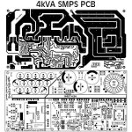
SMPS with PFC
- Thread starter Rookiex
- Start date
Silvio
Well-known member
Hello
greetings wanting to make this smps with guidance from the MAESTRO Silvio
warm regards
Rookie x
Is this your first SMPS? Do you have an oscilloscope? What have you built in the past as this SMPS is not for a beginner. What amplifier are you going to drive with it?
An smps is no joke and care should be taken as it can be fatal for you especially if you do not have the necessary tools to work on it. Please understand that this is a complicated smps and if you do not have experience you will be in for surprises.
Regards Silvio.
Last edited:
res_smps
Member
Dear Rookiex,
for the calculation of the fullbridge transformer you can refer to this http://tahmidmc.blogspot.com/2013/02/ferrite-transformer-turns-calculation_22.html
the number of primary windings for fullbridge smps will be 2 times half bridge smps
for calculation the PFC you can use this spreadsheet View attachment NCP1653 WORKSHEET..XLS.zip
Silvio
Well-known member
Hello Silvio
greetings i have a scope made some simple smps's i would need HELP from you in winding of the transformers
warm regards
Michelle
Ok Michelle so you have an idea at least. Please read the smps warnings on the top of the page. For the Pcb are you going to order it or you are going to make it yourself? Our friend Upik can help you with the pcb. If you are from Indonesia then he can post you one if he still have any left. If you are interested then let me know so that I will contact him by e-mail.
I guess you have to start gathering the necessary parts so that you can start your build. I suggest you start from the PFC stage first and then move on to the smps. I can guide you through the process.
Regards Silvio.
Hello Silvio
greetings and many thanks for replying and being so polite and helpfull .I am collecting parts for the smps
once i have all the parts i will try to order the pcb from jlpcb if it doesnt work out i can make pcb at home
this is an open project for everyone under your guidance this SMPS can be fine tuned even more . I am
from india
warm regards
Michelle
Silvio
Well-known member
I see you played quite a lot with amplifiers and power supplies. I guess you have enough experience to go through this build.
Regarding Upik yes he comes to this forum every now and then. I will ask him if you want to contact him.
Smps
Hello Silvio
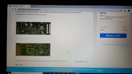
greetings i have ordered the pcbs from jlpcb now i am ordering the parts can you identify IC 1
8pin soic smd beneath the pcb bottom layer
warm regards
Michelle
Hello Silvio
greetings i have ordered the pcbs from jlpcb now i am ordering the parts can you identify IC 1
8pin soic smd beneath the pcb bottom layer
warm regards
Michelle
Attachments
-
 WhatsApp Image 2019-09-02 at 08.42.45(1).jpeg134.7 KB · Views: 99
 -
 WhatsApp Image 2019-09-02 at 08.42.45.jpeg107.8 KB · Views: 72
Silvio
Well-known member
Hello Silvio
greetings i have ordered the pcbs from jlpcb now i am ordering the parts can you identify IC 1
8pin soic smd beneath the pcb bottom layer
warm regards
Michelle
I guess that is the PFC control chip NCP1653.
Regarding Upik I sent him a message and gave him the link, now its up to him.
Silvio
Well-known member
Hi Michelle, The main transformer detail is all in the video. What other problem you have just let me know.
I also wanted to tell you that the chip you asked me about last time it could also be UC3845. This chip controls the auxiliary supply. Please follow the traces on the pcb and you can make out if this is correct. If it's the UC3845 then you shall see some traces leading to the auxiliary transformer on the pcb. I do not have the PDF file for the PCB layout and the one you posted is not very clear and I cannot enlarge it either.
Here are some blog posts to help you out for making a good transformer and also how to make litz wire. download the pdf files attached with the blog posts.
http://www.diysmps.com/forums/entry.php?145-Making-litz-wire-at-home
http://www.diysmps.com/forums/entry.php?143-Transformer-winding-practices-for-smps
https://www.youtube.com/watch?v=_K3ixhcTYFg&t=1s
Regards, Silvio
Silvio
Well-known member
Hello Silvio
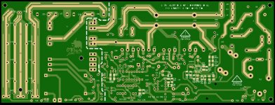
greetings managed to find the schematic of the pcb i ordered please can you check PWM section
is it correct
warm regards
Michelle
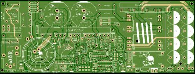
Hi Michelle, Do not be mislead the video in the first post shows a full bridge smps while you are building a half bridge smps. As I can see the pcb takes two kinds of transformer. It either takes an EE55 or an ETD49. The EE55 gives a little more power in fact I got 2KW in my prototype with EE55. ETD49 will give you around 1.5Kw. You must also consider the input voltage with the PFC will be always higher than the maximum AC input voltage.
Let us say that the maximum input voltage of the smps is 254vac then rectifying and smoothing will bring a voltage of around 360vdc. Usually we settle for a voltage of 380-400v. Please also consider your nominal input AC voltage at home and if it is on the lower side like 210vac or lower then it will be better to settle for around 370v or so. I am saying this because the PFC will have enough headroom to boost up the voltage when high load is present.
With all this in mind please let me know what transformer you are going to use and also the core material so that I can work out the number of turns for you. Please also let me know the output voltage wanted. I will also want to know the bobbin length and the window space so that I can calculate how the winding will fit in the transformer. The switching frequency will be adapted according to how things will fit and copper wire used. Please also tell me what switching transistors are you going to use as I have to put the saturation voltage or the RDS on in the software. I also want to know what output diodes for the output you are going to use. I am assuming that this smps is going to be used for audio amplifier.
Regarding the PCB I think all is well and as you start assembling things I will guide you step by step so that you will not blow anything up.
Yes I am on facebook and also watsup. send my an email on silviodeleo@gmail.com and I
give you details.
Here is the link for the HB smps you are building https://www.youtube.com/watch?v=_MHwd7Ro27g&t=1s
Regards Silvio
Last edited: