1000w smps based on LUDO3232

Silvio

Well-known member
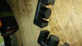
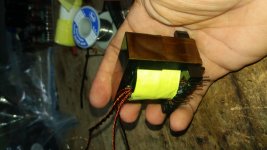
Finally my amplifier under construction, here are some pics and also a pdf file of the construction of this amplifier.
The amplifier can deliver 700 watts into 8 ohms with a dynamic burst of nearly 1000 watts

IMG_0937.jpg

View attachment AMP PICS.pdf

Regards, Silvio
 

behrad

Member
hi
i comeback:D
nice work mr silvio
excellent:UP:
your ampli is stereo and class AB???
700w is very much power.this power is proper for disco.do u have proper speakers??:D
do u have any noise sound in ampli?
 

Silvio

Well-known member
@Behrad

Hi Behrad, My amplifier is class AB and stereo. I tested it with dummy load and oscilloscope.
Yesterday I finished assembly and also tried with 4 ohms dummy load and I got 527w per channel (65v peak on 1KHz tone). I also tested with speakers but small ones about 100w power to check for clarity and It has very good sound and very clear. I do not have any kind of noise with no signal and full volume. The power supply handles the amplifier very well. I need to purchase a couple of good 12 or 15 inch 300w 2 way speakers with tweeter horns for it.
In the PDF file I posted in the last post I have more pictures of the amplifier and also described the things I have in it.

Regards Silvio
 

audiobrad

New member
Hi Silvio, and all diyer's!

I have been trying to repair smps for a while now,some were successful and some ended up in a miniature atom bomb ,lol. reading helps but the best way to understand anything is build it and apply your theory. Safely that is! i will be trying to build the ludo version , i hope i will get some feedback from other diyer's that have built it. Before i forget a BIG THANK YOU to LUDO,MICROSIM and SILVIO . I will keep everyone posted with results as i get on!

Thanks

Brad
 

Silvio

Well-known member
Hello Audibrad,
The circuit of LUDO works if followed correctly, All the information is available on this site and it should be a successful build. When you come to wind the transformer for it I will give you details of the windings according to your output voltage needed. You can also follow the blog posts regarding winding practices and pcb clearances for a safe smps.

Regards Silvio
 

Abet

New member
Hello Silvio,
I finally got hold of a 'scope, it is an old but useful 20MHz. I've been browsing the forum on how to use it in measuring an SMPS. Can you please direct me to a written document if there exists one? I have here a few đocs how to conduct such test, but the mention of a differential/current probe confuses me. My scope does not seem to have the capability to use such probe.

Regards,
Albert

(PM box does not seem to work)
 

Silvio

Well-known member
@ Abet
A differential current probe is the best to have but it is also costly to purchase one. The best way to handle smps is to have an isolating transformer for your smps which has 220v in and isolated 220v out. At least there will not be any ground paths between YOU, the smps and the scope.

The other option is to have a small isolating transformer that can handle the power of your scope to galvanically isolate it from the mains. You still have to be careful though as if you only have the scope isolated and if the casing of your scope and buttons, switches etc are made of metal you can be electrocuted. Current limit for your smps can be made with a 100w incandescent bulb attached with its wires in series with the smps under test.

I hope you have a X10 test probe to measure with. See also the voltage rating your oscilloscope can handle so that it will not be overloaded. Mine can handle 300v.

You can make your initial test before fitting the transformer on the pcb and using an external DC power supply to power up your pcb at low voltage. This way you can see the wave forms and make sure it is working ok before applying 220v to your smps.

I hope this help you to understand a bit what all involves for safety. SMPS do not joke when they blow and great care must be taken on initial power up until you are sure the smps is stable.

I will help you along as you progress and do not hesitate to ask if you need to know anything. I will give you some more tips tomorrow as it is half past one in the morning and I need to go to sleep.

Regards Silvio
 

Abet

New member
Hi Silvio,

Thank you for the quick reply, yes my probe do had X10 and are rated 600V 100MHz. I am using an AVR before the AC 220v wall socket and I do use a series connect 100w bulb limiter. I will be waiting for your tutorial write ups with a keen interest, but I may not be able to reply the soonest as I am currently experiencing internet slowdowns here in my place.

Regards,
Albert
 

eusebio

New member
greetings, fellows of the forum, I have this nucleus destined for this project. I have a doubt regarding its measures not so particular to the models of nuclei used attached image, with this nucleus I would like to work at a frequency of 70khz using igbt any doubt I will be attentive greetings to silvio excellent contributionsIMG-20180220-WA0171.jpegIMG-20180220-WA0171.jpeg
 

Attachments

  • IMG-20180220-WA0173.jpeg
    IMG-20180220-WA0173.jpeg
    950.6 KB · Views: 32
Last edited:

Silvio

Well-known member
Hello Eusebio,

Your core seems to be an ETD 54 This core can deliver quite some power and I guess you can get around 2K at 70Khz

I do not know what are your intentions for this power supply if its for audio or something else.

From what I have seen in your calculations it seems that you need 70v on the output and you have a 110v input.

I can see that this is a used core and you may not know the core material. With this in mind we have to be careful regarding the number of turns used so that the core does not saturate. Keep also in mind that as the frequency goes up the copper wire has to be thinner according to frequency used.

Please say what are you using the smps for and we can make some considerations first.

Did you ever built an smps before?

Regards Silvio
 

eusebio

New member
Greetings Silvio, thanks for replying. if in this case it is for audio 70 volts symmetrical I have organized part of the form of this source little by little to use with the sg3525 and ir2110 controller to work with igbt at 70 khz and have 70 symmetric secondary on the secondary. yesterday I did an essay with a frequency of 80khz and 19 turns in primaryIMG-20180216-WA0185.jpeg
 

eusebio

New member
IMG-20180216-WA0185.jpegthis is my design 15cms by 20cm to handle 3 class d modules with irs2092 the poetection plate is the one from the top of alli it goes straight to the coil of sensing and disconnection of pwm in the igbt I have made sources of lesser powers with nuclei ee42 and good results but I found this nucleus and I'm going to use it for this project. One thing in my region, the network voltage is 110 volts with places where you can reach 117 volts. Greetings, anything that can also help the other members.
 

eusebio

New member
hello silvio thank you for responding in this case as I do not know the material of the core but if I have its measurements by means of the values ​​I mention how many turns I could have to work at 70khz and have at the output 70 volts symmetric any progress I will share it immediate to do the essays I appreciate the help greetings from Colombia
 
Last edited:

eusebio

New member
what type of driver do you recommend? I for the other transformers I have used cable lizz or wire lizt made artisanal mind and I have obtained good resultsIMG-20180204-WA0111.jpeg
 

Silvio

Well-known member
Hi Eusebio, Here is some breifing

As you may well know amplifiers do not draw a constant load and usually they draw no more than 60% and even less of the rated power. This depend also on the type of music played.

Smps have an advantage over a normal mains transformer due to the high switching frequency and also the type of wave produced at the output which is rather square this having a lot of dc content in it compared to a sine wave. Unfortunately it also carries a lot of harmonics with it. Good filtering is needed on the output

The other advantage is that compared to a 50hz transformer the smps has say 50Khz switching frequency, thus during operation when filling back the charge in the secondary capacitors it does this 1000 times faster than a normal mains transformer. The output capacitance is reduced for this reason.

However on the primary side of the smps we need good filtering of the nominal mains input and usually around 2 to 3uf per watt is used. This will give a good punch in the input of the transformer and minimizing voltage drop on the primary winding of the transformer.

In your case I will rather go for 3uf per watt because you have to use the voltage doubler due to the 110 input voltage, I am assuming you are going to use half bridge topology. The minimum requirement for your need is 2 X 3000uf X 200v If you put more say 4000uf it will be better.

On the output side you will need at least 5 to 6000uf on each side and a small inductance of say 10uH
 
Last edited:

Silvio

Well-known member
@ Eusebio

You can still get 2KW at a lower frequency of say 50 or 60Khz. I am saying this because as the frequency rises the wire need to be thinner. With 0.5mm wire you can go up to around 65Khz. If you work at say 40Khz your wire can be 0.65mm.

Please read the blog post regarding making litz wire at home

You will understand why as twisting more than 4 wires tend to make the twist uneven. The larger diameter wire will handle more current and have less losses, it will also occupy less space on the bobbin.

My calculations for current handling will be 30% less than actually needed for continuous rating this is due as explained earlier that amps do not draw constant current.

Calculations

input dc voltage at transformer 155v output peak voltage on secondary 150v (75-0-75) core type ETD 54 material unknown flux we will take a modest one due to the unknown material 1300 guass. frequency 65khz. smps with no feed back thus unregulated

Turns primary 155 X 10^8 / 4 X 65000 X 1300 X 2.83 = 16,2 turns we round off to 16 turns

Volts per turn 155v / 16 = 9.6v per turn

secondary turns = 150v / 9.6 = 15.6 turns so your secondary will be divided in 2 so you will need 8 turns for each secondary

this will however bring the output a little over 70v due that you cannot get an exact voltage. Keep in mind that this voltage will fluctuate according to the input AC voltage and also will sag with load and with the voltage drop in the diodes and output inductor.

Ampere turns current density is 8 amps per mm²

You will need 3 bundles of 3 wires twisted together (total of 9 wires) 0.5mm dia for primary and also for each secondary

Peak current in primary is 17 amps at full load of 2000 watts

Peak current in secondary 16 amps at full load

auxiliary winding to power fan for cooling 2- 0- 2 turns for 18v out you need to put 12v regulator to stabilize for 12v

It is advisable to read the blog post regarding transformer winding practices to take an idea what to do for a safe transformer. Please use the instructions given and also use recommended tapes. Do not forget that if the primary leaks with secondary the smps can kill you.

Regards Silvio
 

eusebio

New member
hi silvio I share the advances transformer with windingsIMG-20180225-WA0024.jpegIMG-20180224-WA0200.jpeg
 

Attachments

  • IMG-20180224-WA0196.jpeg
    IMG-20180224-WA0196.jpeg
    862.7 KB · Views: 64
Last edited:
Top