1000w smps based on LUDO3232

Silvio

Well-known member
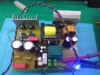
It looks you progressed quite well Eusebio, the only missing thing that I can see is that you did not use any sleeving at the ends of the windings. Some heat shrink tube would have done the job.

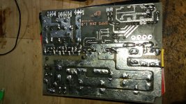
I do not know if the center taps coming out of the top are all common to each other. Here as well some sleeving would have helped for better insulation. Apart everything else it is a neat job with the trafo and also the pcb

I guess the trafo is ready now but for future transformer windings I suggest you take a look at my video on youtube called Winding small transformers for smps. This will help you out learning good practices.

here is the link

https://www.youtube.com/watch?v=_K3ixhcTYFg

Regards Silvio
 

eusebio

New member
olhello silvio if you use thermo-shrinkable for the output lines of each debanado to avoid future short circuits and good is already advanced and completing the pwm stage and current sensing, read your post on the calculation part of the sensing transformer where you speak to make a double debanado for better precision you could do some drawing or explain that part very grateful friend. this week I'm adding the other photos of armed and measurements of door in the gate of mosfet greetings. as for the winding video if I had already seen it excellentIMG-20180226-WA0234.jpeg
 

Silvio

Well-known member
Hello Eusebio, I see you advanced quite well in your smps. I would like to see some more pictures of the PCB, possibly one from the top to see it all and also one from the underside. I hope you left enough clearance in the traces on the high voltage side.
You can also post the schematic of your work so that I can tell you about the current transformer and other things.

Regards

Silvio
 

eusebio

New member
hello silvio greetings, this time I sent the diagram of which I followed instructions to make my pcb. I made a modification in the sensing part omitting the ic555 ppr a pic that is responsible for doing the same function and veeificar by means of a zener the voltage in the secondary acting as a low voltage sensor and sent the photos of the design and printed I like to work with ExpressPCB. the designs is very easy to handle and you can create very easy components with the. In the version of the protection I have doa options the design to follow that is the scheme that I mention with a slight modification in the value of the resitor trimer, unlike of your design that is taken as value 500 ohms I attach the images
 
Last edited:

Omid

New member
Hi . This is seem very good. But i want tu change the out put 24 volt and 50 amper. How i can tu change this?
 

eusebio

New member
in my case to get that voltage were around 7 laps but touch looks at what frequency of work you have your oscillator circuit ir2110, sg3525, or if you are using another type of driver and for that current you can use igbt or FDA50N50, working at a frequency with this mosfet around 80 to 100khz, correct me if I'm wrong silvio we are to collaborate and what I can contribute for my essays here I will be. oo I forgot, the page has not allowed me to load the other photos of the diagrams to which it was previously possible to do it and now no!
 

Silvio

Well-known member
Hello Eusebio,
I am sorry to say that the spacing in various parts of the pcb layout is not so good. The spacing between the traces regarding high voltages are too small. These should be around 3mm apart. These include the mains input and also the 300 volt rails.

If you want to remedy this problem you can use a sharp knife or a broken hacksaw blade and ruler and scrape away some of the traces to widen the clearance for at least 2mm . You must also cover that fuse because it is very near the heat sink. You should also clean the underside of the pcb from rosin (flux) with solvent like cellulose thinner or acetone. It is very important to keep the pcb clean as traces can easily leak with each other and you end up in a catastrophy, not to mention getting yourself electrocuted.

When all is ready you must use some lacquer spray on the traces to seal out moisture. I use normal transparent cellulose lacquer spray found in hardware stores.
Do not forget that when everything is fitted in the amplifier dust tend to get in the box with the fan running and moisture and dust tend to short out the traces of the pcb. You must protect the pcb because of this.

Regarding the delay circuit it does not make any difference which circuit you use as long as it works properly with adequate timing.

The schematics you are following are more or less the same apart from one of them having feedback and more capacitance in the output.
In my schematic the 500 ohm preset adjust the dead time of the oscillator. You can put a fixed resistor once you find the right value.
My smps dead time is 1uS. R7 attached to pin 9 on my schematic will not allow you to go down below 1.5uS so you may need to change it to 820k instead. Be careful but if you do not have an oscilloscope do not touch it as you cannot see the dead time. You can drive the oscillator pcb separately and set the dead time first and see that all is correct before you power up the main pcb.

Lastly you need some support in the center of the pcb as this may bend with weight and also while testing and the underside may touch the chassis of the amplifier box

Please be careful while testing and powering up the smps.

Regards Silvio.
 

Silvio

Well-known member
I followed the design below just do not use ic 555 which changes for a pic, as for the protection by sensing in the primary stage I have that doubt using trimmer of 20k 0 500ohmsView attachment 6563View attachment 6564

For the trimmer you can use what ever you like between 500 ohms and 22K. In my case I used 500 ohms because the voltage across it is only 5v so the current is 10mA and power dissipation is 50mW. The trimmer is rated for 250mW. For larger value trimmer this will be less current and wattage.

The frequency of operation of my smps is 62Khz. I used 0.5mm wire so frequency cannot go beyond 68Khz due to skin dept.

Silvio
 

zoky2

New member
Protection problem

Hi,
here is my second attempt to 1000w smps.It works at 85khz ,output is +-80v DC and will power 4 channel class D amplifiers. One channel is in the picture. The smps works good, at idle only transformer get a little warm ,anything else is cold. But I have problem with current protection, cant start smps with protection without a bulb in serial with input voltage (230 AC). The protection trip every time with or without load on secondary side if I connect smps direct to mains.Without protection I can get 5A current at output with 10V dropout and not much heating of any component.The current trafo is toroid with 50 turns for secondary and 1 turn for primary,the rest components are the same value as on schematic .Can anybody tell me how to fix that problem?


Regard
zoky 2
 

Attachments

  • IMG_20180309_101139.jpeg
    IMG_20180309_101139.jpeg
    127.4 KB · Views: 118
  • IMG_20180309_101057.jpeg
    IMG_20180309_101057.jpeg
    134 KB · Views: 85

Silvio

Well-known member
@Zoky2

Dear Zoky, If the schematic that you followed is the one found here of LUDO 3232 then the turns for the overload trafo must be 22 turns and not 50. The load resistor is to be 10 ohms 1 watt.
Once you start up the smps you should load it gradually to full power with resistive load like heater or bulbs etc until you arrive to a load of 7 or 8 amps. You should adjust the overload preset gradually until the smps trips on overload at the wanted output current. I can also see that the output inductor is a bit large and this will increase your voltage drop at the output.

I hope that helps

Regards Silvio.
 

eusebio

New member
hello silvio after a short break I made the adjustments that you had recommended me, currently the source is working with 65khz and igbt G4pc50U trafo delivering 78 volts symmetric attached photos. As for the protection is working well use resistance to sense of 22ohms 1w and serca 30 turns in iron powder core. use resistive load of 1500w microwave resistors protection set in 17ampIMG-20180318-WA0040.jpeg
 

Silvio

Well-known member
Hello Eusebio,

I can see that the you set the trip current to 17 amps. I do not know if the voltage on the meter is with the smps fully loaded or on idle.
You must measure the output voltage while the smps is loaded to see what is the power that you are actually absorbing.

Power = volt X amps.

My smps drops from 160v (80-0-80) to 140v at a load of 9amps.(1260W) (The trip current is set to 10amps. around 1400w)

I am not using output inductors and ripple voltage is 4v peak to peak at full load.

I gave you my results for you to make some comparison.

Regards Silvio
 

Booker

New member
Hi
how many turns do i need for an etd49 primary and secondary? I need a secondary voltage at 80V and how many auxilary turns do i need?Sorry for my bad english!!!
 

Silvio

Well-known member
Hello Booker,

You need to give more information about your transformer as follows:-

What is the core material (example PC40, N87, N27 etc)?
What frequency are you going to run your smps
What topology are you using (half bridge, full bridge etc)?
What is your nominal grid voltage (220, 230, 110, 120)?
Is the smps regulated or not?
What power are you looking for?
Purpose of smps audio or something else?

Regards

Sivlio
 
Last edited:

Booker

New member
Its your smps from this thread,core material is N87 ,the nominal voltage is 230V and it is for audio. I think for Primary 18 turns and Secondary 9-0-9 turns is this right?
 

Silvio

Well-known member
@Booker

Yes with those turns you will get a little less than 80v at 230v but if the input voltage is around 240v then it will peak 80v.
The volts per turn ratio is 9.4v per turn.

Another combination you can use is to wind the primary with 20 turns the secondary with 10-0-10 turns this way at 230v you will have a peak voltage of 325vdc dividing this by 2 will get a primary voltage on the Half bridge of 162v so to get the volts per turn this time we divide 162v by the number of primary turns (20) we get 8.1v per turn. so for secondary 8.1 x 10 we get 81v.

Well it all depends on what your amplifier can take as maximum voltage.

The example above will give you a good idea how to play a little with turns. However do not go below 18 turns and more than 22 turns for primary windings. The turns described are suitable for a switching frequency of 60 to 65Khz

In my smps I finally removed the output inductors and got less voltage drop at load. I also added a 1uf polypropylene caps across each output to center ground. This helped further more with filtering the noise in the output.

Regards Silvio
 
Last edited:
Top