1000w smps based on LUDO3232

Silvio

Well-known member
@ Upik

If you are using my pcb then you have a separate PWM board from the main pcb. You can follow the supply rails to it from schematic.

feed the supply rails with 12vdc and observe polarity +/- to be correct

Put 2 leds with the outputs of IR2110 and put also 1K series resistor with each led then put the other end of the resistors to ground.

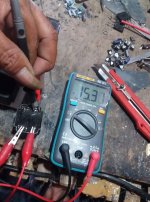
if the leds light up it means it is working. This is only indication because you cannot see frequency without oscilloscope. You can use frequency meter and measure output frequency by measuring it on the outputs of IR2110 this should be set to around 63 Khz. If you don't read frequency it means that it is not working and something is wrong.

You can ask a friend maybe he can help you with borrowing frequency meter. Lot of Digital multi meters can measure frequency.

See that you buy genuine chips as fakes may not work and blow up your fets.

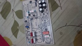
Look at the picture in the PDF file of me trying out PWM board.

For the center of the primary you can just fold and continue winding after you wind secondary, Center of primary is NOT connected to anything.
 
Last edited:

Upik

Member
@mr.silvio

Thanks for your help. I have esr meter to know the frequence. Can you direct me, how to make faraday screen on the transformer.

I have finished the pcb part. It seems like i need a long time to assemble it, because now i am in work. I do this smps at night, after i go home to work. Thanks many mr.silvio.
 
Last edited:

Upik

Member
@Mr.Silvio

For dead time I want to follow your instructions, I want to replace vr2 with 33 ohm resistor. Is it correct right mr.silvio ???
 

Silvio

Well-known member
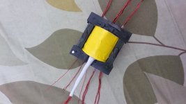
The trafo looks ok I hope you observed the margin clearances well and also put insulation sleeve on the ends of the primary windings.

For the dead time yes you can put a 33 ohm resistor instead this should give you approximately 1.2 to 1.5 uS dead time

I was just wondering what are you going to use as an auxiliary 15v power supply. Are you going to fit one externally to the pcb?

Regards Silvio
 

Upik

Member
I have used 0.5x3 wire ,,,,, 2 bundles to be rotated together on primer, and 3mm margin on each side. For secondary 0.5x4 ,,,, 2 bundles in swivel together, and 6mm margin on each side, yes i have used sleeve in each primary and secondary

I have 22 rounds for the primary, and 12 rounds for the secondary.

For external 15v power supply I use a small transformer. But i have not finished pcb for it. I also want to add 5v power supply on it. To supply my mp5 module

FB_IMG_1523971590866.jpg
 
Last edited:

Upik

Member
Well, thank you very much for your help, I will show you my project result, after I have finished all the parts
 

Upik

Member
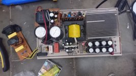
Hi mr.silvio ,, i have resolved all the parts. And i am eliminating the inductor output. But i am having problem is on the extra output resistor part 15v. In the minus part lane. With 4R7 value it burned and let out smoke, i replace it with 10 ohms, and it's the same, keep burning, how the solution from you, ???


DSC_0243.jpg
 

Silvio

Well-known member
The resistor is in series with the minus trace so that if a short is present at the regulator it fuse up. Well try to remove the 7915 regulator chip and see what happen. I think your negative regulator chip is burnt or short circuit. It could also be that you did not use insulation behind the IC regulators. Be careful as the tabs are not common to each other.

The reason I used different series resistors is because on the positive regulator there was the load of the fan motor and I needed some more current for it. That is why the 4.7 ohm resistor and not 10 ohms like the other
The other 10 ohms resistor in series with the fan socket is to reduce the voltage from 15v to 12v to the fan motor.


I hope that helps
 

Upik

Member
Thanks for your reply mr.silvio ,, it is very helpful, and I have found my problem solution, it turns on the regulator heatsink 7915,, that has short regulator, I think I have solved the heatsink surface, because bolts keep connecting regulators and heatsinks directly, I have to separate the plus and minus voltage heatsinks on the regulator, and now I am returning to give 4.7 ohm resistor
 

Upik

Member
Next I have to test the smp with the load. Therefore I have not done, what about the halogen load 300watt and 500watt, both connected by way in series or parallel ??
 

Silvio

Well-known member
Next I have to test the smp with the load. Therefore I have not done, what about the halogen load 300watt and 500watt, both connected by way in series or parallel ??

Well what is the voltage rating of the halogen lamps? please tell me also the full voltage from the smps.
You can load halogen bulb gradually but be careful as the cold filament will draw a lot of current until it warms up and may trip your overload protection.
You need to put ampere meter in series and also volt meter in parallel to read the output watts.
See if you can find old heater element and use it as load.

When you get the maximum load you can adjust the trimmer so that the smps trips at the wanted current.
 
Top