1000w smps based on LUDO3232

Silvio

Well-known member
Yes it means I have to use 8 diodes now ,,, i have to adjust the resistor which was 2.2k if it was before the zener, .but i should be able to power me if in view of the datasheet of the bias transistors there. To give them 50v power supply. I will try it. i will take all the resiko.jika it made a mistake, maybe i should learn to make class D.mungkin.saya ever read it power class d belong to norazmi.

You have to adjust resistor which was 47K and not 2.2K. I said put 33K instead for 50v if you want less voltage then use less like 27K or so. You can put preset resistor till you find correct value then put fixed resistor.

I did read posts from Norazmi and also from Stewin, I never built class D amp, They are very cheep to buy from E-bay or Aliexpress they are very powerful and small in size

https://www.aliexpress.com/item/IRS...805af34&transAbTest=ae803_2&priceBeautifyAB=0
 

Upik

Member
Hi mr.silvio ,, ye i understand now. I want to ask about the primary transformer scroll, which one is better, 18 rounds for primer, or 22 rounds, because the transformer I use now has 22 turns. If i use 2 bundle 0.5x3 ,, if 18 rounds, what is the distance of margin, if if heat transformer will decrease performance, ???
 

Silvio

Well-known member
Hi mr.silvio ,, ye i understand now. I want to ask about the primary transformer scroll, which one is better, 18 rounds for primer, or 22 rounds, because the transformer I use now has 22 turns. If i use 2 bundle 0.5x3 ,, if 18 rounds, what is the distance of margin, if if heat transformer will decrease performance, ???


The number of turns all depend on the type of material in the transformer. The N87 type or PC40 can take 18 turns primary at 65Khz.
The transformer will work with a flux density of around 1600 guass.

If the material of the transformer core is not known it is better to use 22 turns for primary because not all material will have the same effect with same number of turns. If flux density is too high then transformer could saturate.

Regarding the margin clearance it is important that you do not have less than 2mm on the sides of each winding. If there is more no problem it will work the same

For current handling of copper wire we use 6amps per mm² For Audio

so for 6 wires by 0.5mm = 0.25 X 0.25 X 3.142 = 0.1963 mm² This is the area of 1 wire

for 6 wires = 0.1963 X 6 = 1.1778 so for audio we use 6 amps per mm² so 1.1778 X 6 = 7 amps.

7 amps are a little low for 1200 watts primary current for 1000w = 1200w / 155v = 7.7 amps

I used 1200 watts because the smps will be around 80% efficient so to give 1000w smps will consume around 1200w in primary

I think that 7 wires will be more appropriate

In my SMPS I used 8 wires for primary and also 8 wires for secondary of 80-0-80

Your smps at 100 volts secondary will consume 10 or 11amps

So you need 0.196 X 10 wires = 1.96 mm² X 6 11.7 amps

Regards Silvio
 

Upik

Member
Hi mr.silvio ,, i really have a problem now, i have put it together with my amp power, when turning on smp protect ,, how to solve it like that, my smp ?? if directly connected to load when start always protect.

He does not want to be directly connected to the load. In fact I have not connected to Speaker yet
 
Last edited:

Silvio

Well-known member
Hi mr.silvio ,, i really have a problem now, i have put it together with my amp power, when turning on smp protect ,, how to solve it like that, my smp ?? if directly connected to load when start always protect.

He does not want to be directly connected to the load. In fact I have not connected to Speaker yet

What is the current set of the over current protection in your smps?

Do you have more capacitors with your amplifier?
 
Last edited:

Upik

Member
Hi mr.silvio ,,, inside my amps box, there are 2 power, yes i connect with 1 power, it runs without any problem, and for its 1 power, that is the problem, it is true for power 1, he has many capacitors. how is your solution, ???
 

Upik

Member
Is it possible i try to remove its protection, ??? how can i remove the protection mr.silvio, ??? pin 10 on Sg3525 can it be connected directly on ground, ???
 

Silvio

Well-known member
I do not suggest you remove protection.

Here are some modifications you can make.

1) Change C22 (330pF) to 0.01uf ceramic on protection section input of LM393

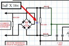
2) put small electrolytic cap 1uf X 16v across R11 (check for correct polarity) this is across secondary of sense trafo

3) Change soft start cap near SG chip C18 from 22uf to 47uf

4) Change R2 near input from 100k to 220k for longer delay before relay will latch

Make modification one at a time start from No 1 and progress to the others. Leave every mod in place and proceed to the next until you get a good result

Regards Silvio
 
Last edited:

Upik

Member
Ok mr.silvio, for r11 in schematic there are 2, which one is right,? For capacitor by way of series with resistor or parallel, ???
 

Silvio

Well-known member
You need to make another soft start to switch on the amplifier after the smps has come on. Put series resistor feeding the amplifier and after 1 or 2 seconds a relay will short out resistor. This way there is current limit going to charge up the capacitors of the amplifier.

What is happening is that with the added capacitors the output of the smps is seeing a dead short you need another soft start with amplifier

I hope that your amplifier has no short circuit in it

You can build a similar delay timer like the one on the smps a small pcb and timer 555 and 12v relay DPDT. Put 22 ohm resistor 5w in series with supply rails +/- one on each side,( these will limit current to 2.5amps at 50v) then after amplifier capacitors charge up relay will close and short out current limit resistors(22R) and supply will now pass direct to amplifier

regards Silvio
 

Silvio

Well-known member
How do I remove its protection, pin 10 Sg3525 directly to ground how, ???

You did not say at what current you set the over current trip. Did you load the smps to full load and set over current protection?

you need to load at 12 amps on output.

You did not say how much capacitance you have in the amplifier

You can disconnect one of the secondary wires of the current transformer and SCP will not operate.
 

Upik

Member
Hi ... mr.silvio seems there is a problem in my power. I have to check it it. I apologize if it has much trouble you
 

Silvio

Well-known member
Hi mr.silvio ,, How can i set ocp to 2 ohm load, ??? how many ohms on your spiker now, ??

My speakers are 8 ohms.

To set ocp on smps with the amplifier at 2 ohms load. I does not really make a difference on the smps. If you set the current well on the smps then it will trip when peak current is reached.

If you want to protect your amp then you have to load amplifier to maximum load with 1Khz pulse then you can set the smps to trip a little higher than the peak of the amplifier.

Silvio
 

Upik

Member
Hi mr.silvio ,, now i have a new transformer, ie ee65,, can it give more power than etd49, ??? or if i use ee65 need to add GDT, ??
 

Silvio

Well-known member
Hi mr.silvio ,, now i have a new transformer, ie ee65,, can it give more power than etd49, ??? or if i use ee65 need to add GDT, ??

At 60Khz EE65 can deliver 5500w or more. You will need thicker wire in transformer better output diodes and better switching mosfets or IGBTs that can handle 40amps or more. You need to re design the pcb for heavier current in the output. You will need more input and output capacitance.

Regards Silvio
 
Last edited:
Top