You are using an out of date browser. It may not display this or other websites correctly.
You should upgrade or use an alternative browser.
You should upgrade or use an alternative browser.
1000w smps based on LUDO3232
- Thread starter Silvio
- Start date
Silvio
Well-known member
What if I add a load of clothes iron, because I think the iron in it there is a heating element.
Yes you can try with electric iron or even electric kettle if you want.
To calculate watts you will need at least 11 or 12 amps of current on the output for 1000w.
Yes I do not have any heating elements other than solder, halogen lamp 220v, and my smp is 100v peak. For protection can i arrange with vr3, ??? if gradually means the light load must be connected in parallel between lamp 1 and the other. is that like mr.silvio, ??
What I mean by loading gradually is that you parallel several loads one at a time so that you can test where the over current trip will activate.
I mean to combine 300 watt halogen and 500 watt, it's in pairs 300w series with 500w, or parallel between halogen 300w and 500w, or both will be the same. If halogen like resistor then if both in parallel then resistance will decrease. like that I mean I have tried with 2 halogens in parallel, I think with only 2 halogens it still does not have enough load. maybe i should look for water heater, for extra load.
Well mr.silvio, I am very thankful to you, who has allowed me to make smp from you. At least I have managed to build it. Now can you help me, how can i manage this smp, at least using opto.karena home electricity not so stable , and also there is no decrease in the output voltage. at least you can give me the schematic in the opto circuit, which will connect to pwm ic foot.
Silvio
Well-known member
Hi Upik, I don't know why you need feedback. If you have 50v peak I think amplifier will be happy. The variation in input mains voltage will not make a lot of change in output voltage.
If there is no decrease or little decrease in output voltage it means that you have a stable and strong smps. It could also be that you are not loading it enough to see it.
Usually the decrease from no load to full load will be between 10% to 15% which at 50v less 10% = 45.5v
(45+45) 90v X 12A = 1080 watts
I have options for feed back but you need to modify pwm board and also make extra pcb for opto and reference IC and resistors.
With modification dead time will change and need to set at new value with oscilloscope.
You need to add output inductor and for stable output voltage you need to have around 20v more than regulated voltage.
My smps has 80v peak and can regulate for 60v . I did not make output regulation for my amplifier and left it 80v-0-80v
With output inductor there will be more voltage drop at load and you need also to filter noise on output. and make also secondary snubber.
I think you better leave smps as it is as it will get complicated and you have no scope to see what is happening.
Take a look at my Amplifier https://www.youtube.com/watch?v=sHH2GMITc7E&t=6s
I have removed the inductor output, and i replace the c filter with 1uf, should i add secondary output snuber, ??? yes if you are willing to give the feedback option it sounds fun, I want to change the layout of you, without changing the value of the component, I use eagle pcb.itu if you really give feedback option, and with your permission. previous
Silvio
Well-known member
I have removed the inductor output, and i replace the c filter with 1uf, should i add secondary output snuber, ??? yes if you are willing to give the feedback option it sounds fun, I want to change the layout of you, without changing the value of the component, I use eagle pcb.itu if you really give feedback option, and with your permission. previous
If you opt for feedback then you will need output inductor. You can make two separate inductors or use only one ring it is your choice. Value of inductor is 15uH for each rail. If you use only one ring for both inductors then the winding sense has to be one opposite to the other.
You need to set dead time as now the 470k resistor on the pwm board is removed. You need higher resistance.

1000w smps it has different winding for 80-0-80 peak and can regulate to 60-0-60 with the same transformer. I will upload version 2 file for you
Regards Silvio

View attachment 1000W smps V2 final.pdf
Hi mr.silvio ,, thanks a lot, it means i have to slightly change pwm board, remove r470k, and change c16 with 100n value, also add r1k on pin 9 to ground. For opto circuit can i just use r on pin 2 opto to output min and some zener on pin 1 opto to plus output ,, i need to change the dead time resistor with value greater than 33ohm or maybe same mr.silvio, ???
For current transformer, if want to enlarge the current how about the secondary winding? The less the winding will the greater the current or multiply the winding for the greater the current in the OCP settings, ??
For current transformer, if want to enlarge the current how about the secondary winding? The less the winding will the greater the current or multiply the winding for the greater the current in the OCP settings, ??
Last edited:
Silvio
Well-known member
Hi mr.silvio ,, thanks a lot, it means i have to slightly change pwm board, remove r470k, and change c16 with 100n value, also add r1k on pin 9 to ground. For opto circuit can i just use r on pin 2 opto to output min and some zener on pin 1 opto to plus output ,, i need to change the dead time resistor with value greater than 33ohm or maybe same mr.silvio, ???
For current transformer, if want to enlarge the current how about the secondary winding? The less the winding will the greater the current or multiply the winding for the greater the current in the OCP settings, ??
I tried using only zener and opto but it did not work good for me. I find better regulation with TL431
Modifications are all correct on version 2 schematic. You will also find small pcb for feedback in file
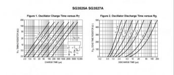
For the dead time I set it again on scope and do not know the actual resistance now but I posted chart for you to calculate. If it is not clear enough you can download datasheet of SG3525 you find it there . Resistance must be larger value. I have my PCB assembled in amplifier and cannot measure it now.
For current you can enlarge by using only 1/2 turn loop on pcb with current trafo instead of 1.5 turns. You can also make less turns on secondary like 20 turns instead of 22 or you can also make smaller load resistors instead of 22 ohms. With values shown on schematic it can go up to 13 amps on secondary.
Silvio
Well-known member
What happen is that if dead time is too short you may have shoot through ( means one mosfet is still switching off while the other is switching on and Bang!) If dead time is long you loose power from smps.
You could try with 120 ohm resistor instead of 33 ohms see how it goes. I am not sure about this value but should give enough dead time i guess. You really need oscilloscope to see dead time.
I cannot tell you my value I have smps assembled in amplifier and backside is all lacquered
You could try with 120 ohm resistor instead of 33 ohms see how it goes. I am not sure about this value but should give enough dead time i guess. You really need oscilloscope to see dead time.
I cannot tell you my value I have smps assembled in amplifier and backside is all lacquered
Hi mr.silvio ,,,, you are a great teacher, thank you very much for teaching me and help me, i can not repay your kindness .. i want to be your student, sometime if i have oscilloscope i want to learn a lot with you , surely how to use it. if you do not mind ,,, for resistor in series if 33k will make the voltage 50v, meaning every 1k represents 1.4v ,, right so mr.silvio, ???
Silvio
Well-known member
Well not actually as you say but we are putting enough current to the reference diode (TL431). The 33k resistor limit current through the zener and has to start conducting as 50v is reached. The regulated voltage 33v will supply the reference until 2.5v is reached then it will switch on the led inside the opto and the transistor start reducing the pulse width at the pwm. You can also see that we have the same reference at the sg chip and the voltage is divided from the reference of 5v with two resistors 10k. What happens is that the one reference (tl431) tries to get the same reference on the sg chip hence the output is regulated.
To maintain this voltage you must have a small load at the output. The load may be a little critical as the voltage must be kept constant with the help of the output inductor. If the inductor is too small then there will be hunting of the output voltage. I think with 15uH you can work out ok with a small load of say 20w. if you need smaller minimum load at output then you need more inductance like 20uH or 30uH.
Be careful but as the more inductance on the output the more voltage drop at load, you must find a good balance between these two.
Regards
Silvio
Well mr.silvio ,,, I have 2 power in 1 box, because I make my power in 2.1 ... and for 2 stereo chanel seems only able to give 35v power supply until 40v ,, yes I never give about 50v more, and it turns out the bias transistor explodes, either because of excess power supply or maybe there is a resistor that changed the value. or maybe i did not use softstar. the 1 channel for sub is able to be given 80v. how is your solution, ??? what i have to decrease in 40v only , ??? i do not see you build an Amplifier class project d ... i hope you as teacher will do it
Silvio
Well-known member
Hi Upik you did not say that you need 2 voltages. It will get complicated for you now.
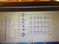
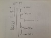
One solution is to wind again the transformer and have 2 bridge rectifier and capacitor bank.
in the pictures you will see how to make it. And you don't need feedback


If you want to use feedback and bring down the voltage of the output to 40v then you have to reduce a little more the resistor before the zener and it will be possible to get the output to 40v. You can also put a 47K preset to see what value you need and then put a fixed resistor instead when the correct value is found.
Regards Silvio
One solution is to wind again the transformer and have 2 bridge rectifier and capacitor bank.
in the pictures you will see how to make it. And you don't need feedback


If you want to use feedback and bring down the voltage of the output to 40v then you have to reduce a little more the resistor before the zener and it will be possible to get the output to 40v. You can also put a 47K preset to see what value you need and then put a fixed resistor instead when the correct value is found.
Regards Silvio
Last edited:
Yes it means I have to use 8 diodes now ,,, i have to adjust the resistor which was 2.2k if it was before the zener, .but i should be able to power me if in view of the datasheet of the bias transistors there. To give them 50v power supply. I will try it. i will take all the resiko.jika it made a mistake, maybe i should learn to make class D.mungkin.saya ever read it power class d belong to norazmi.
