Audio smps 700w (IR2153)

Silvio

Well-known member
@ Steppler

Some more considerations

1) input soft start missing+ bridging triac or relay missing
2) input fuse missing
3) safety ground capacitors missing 2 X 2.2nF X1KV
4) grounding of the negative output terminal missing
5) 1uF capacitor in parallel with output capacitor missing
6) Grounding of the SMPS is non existent.

If something happens and the primary of the transformer shorts out with the secondary you will see God prematurely.

Regards Silvio
 

steppler

New member
@ Silvio

This is input power board:

ipw.jpg

Among other things include softstart. 2s delay relay bridged resistors 40ohm 20W.

Fuse to rear panel.
 

Silvio

Well-known member
@Steppler
That is much better. You showed a very basic schematic at first with a lot of things missing in it. By the way the pcbs you are making are very nice and looking professional.

One other thing you should add is a 4.7nF capacitor from the high voltage ground to the negative ground of the secondary plus another capacitor 4.7nF from the negative of the secondary side to earth ground, this will protect both for EMI and also in the event of a short in the transformer windings (primary to secondary) it will find a path to earth ground and will trip the earth leak circuit breaker in the grid. One other choice is to ground the secondary negative terminal to chassis. If you have a double winding of say 30-0-30 then ground the center ground to earth ground. Take a look at my PDF file it can be downloaded on page 2 post #13. There I have a ground path which connects to chassis via the stand off pillars. Taking a general look you will see these capacitors I am mentioning, they are ceramic caps rated at 1kv.

Did you get rid of the stray voltage?

Regards Silvio
 

steppler

New member
I changed the transistors to IRF740, I added the snubber. Result? .... 90V !!!!

I disconnected experimentally output coils and 2 capacitors ..... increase to 95V.

And transformer is very hot.

I will try to add ground capacitors.

The experiment continues ........ my name is Don Quijote ......
 

Silvio

Well-known member
@ Steppler
Did you wind the transformer yourself?

This is very odd Iwound a lot of transformers and this issue never happened to me. As I said before without a scope you are blindfolded.

The transformer getting very hot is not a good sign and it could be that something may be wrong with it. (There should be no gap in the center leg of the core for this topology (Half bridge) Try to change the IR2153 and see that it is genuine.
Please check if the output diodes are in the right orientation as I am suspecting that you are having a voltage doubler effect.
It could be also the case that the windings are in series aiding and doubling the voltage somehow. I am trying to figure out what may be wrong and these are only assumptions. The circuit is very basic and has been built by a lot of people but these mishaps have not been encountered before apart of a faulty chip or something that I mentioned before.

Put a series 100w Lamp with your input wiring. You can attach it instead of the fuse. This will help in the event of something is wrong. The bulb should light up briefly and extinguish again on start up due to charging the main bulk and secondary caps. The filament should show no signs of glowing during operation of the smps without load.

I suggest that you take a look at my Youtube video ( Winding small transformers for SMPS) This will help you out for a good safety transformer build Don Quijote LOL.

Link https://www.youtube.com/watch?v=_K3ixhcTYFg&t=1s

regards Silvio.
 

blasphemy000

New member
I've just been glancing over this thread, but here is my thought.

I'm assuming your input voltage is 220-240VAC. Rectified and filtered this would be around 340VDC, give or take a little bit. You are running a half-bridge topology, so the voltage being switched across the primary of your transformer will only be half of your input bus voltage, so about 170VDC. Now, given the details of your transformer, your turns ratio is 3.54:1, the maximum peak voltage coming from your transformer absolutely cannot be higher than 48 or so volts.

Now, having said that, I can only think of two possibilities of what is going on here.

1.) The primaries of your transformer accidentally got connected in parallel instead of in series. This would cause the output voltage to be doubled, but also would most likely cause the transformer core to saturate (or get really close to it) which would cause the output voltage to drop significantly under load and cause the transformer itself to get quite hot. This would also cause heating in the mosfets and could also cause them to fail.

2.) The transformer is being driven as a flyback transformer. For example, if one of your mosfets isn't switching properly. These IR2153 chips tend to be quite fragile and I've seen many examples of the high-side driver just completely not working at all. If you've ever had a mosfet fail on this circuit, you should replace the IR2153 at the same time you replace the mosfets, because it is most likely failed also. In this case, if only your low-side mosfet is working, this could cause your transformer to saturate, run very hot, and due to the inductive flyback effect, cause a very high output voltage under no load conditions with a severe drop in voltage with any significant load applied.

Your transformer only has a single secondary winding, so I'm not at all worried about the connections on that side. If the output diodes were reversed, it would either dead short the output (quickly killing the output diodes) or cause no output voltage at all.
Without a scope you're just shooting off in the dark here, but those are my two ideas. Good luck and I like the professional board design.

- Brad
 

steppler

New member
Hello I'm back.

I measured transformer primary frequency ..... 92kHz !!!! That's weird !!! Rt=15k Ct=1n This is cca 50kHz. Puzzle ?????
 

Silvio

Well-known member
Hello I'm back.

I measured transformer primary frequency ..... 92kHz !!!! That's weird !!! Rt=15k Ct=1n This is cca 50kHz. Puzzle ?????

Try to change the IR2153 and see if you have the same result, You can also change the timing resistor or capacitor until you get the right frequency
 

Holgin

New member
This is my first post here, so - hello everyone! :)

I have finished a 2 layer PCB layout for IR2153 project . The main difference is that I need only one secondary winding - 55V and as much Amps as possible :)
It is based on the schematic from here:
http://www.diysmps.com/forums/showthread.php?733-Another-IR2153-smps
All designed to use parts from old ATX PSUs. Normally I would not bother and just buy a 500W PSU, but:
-I need at least 4
-I want to learn something!

I am using an ERL-35 transformer. Various datasheets state that I can get 350-400W from it. With active cooling I hope I can go for 400-450W ;)
As I have no real experience with SMPS design, I would like to make sure that the PCB layout is at least acceptable.

I want to go for 70...100kHz. At this moment I want to mention that I am not sure how to calculate the copper diameter for the secondary winding. If I use AWG25 (0.457 Amps), I need to use about 20 wires to handle ~9A? It would be very difficult to wind that.

Back to the SMPS itself - I want the output ground to be isolated, because I will be connecting these SMPSs in series. Can I throw out C16?

Here you can find the documentation:
https://imgur.com/a/eLoqEG7
PDF file:
View attachment SMPS docu.pdf
I will appreciate any suggestions and tips.
 

Silvio

Well-known member
@Holgin

As far as the layout of the pcb looks ok to me. Regarding C16 this can be omitted but there will no path for safety if the primary leaks with secondary windings and it will bring the smps secondary to mains potential.

You will need to leave some margin space at the cheeks of the bobbin for safety around 2mm on each end on each winding.
The wire you are using is fit for a switching frequency of 80Khz. I would suggest not going beyond this frequency as the switching losses will become quite significant.

The current density of the copper wire is calculated at 6A/mm^2. Forced cooling is necessary for continuous use. You will need to add more copper for 100% duty cycle and current density will be more like 3A/mm^2. This will not fit however in your existing erl35 core and in case you will need a bigger core

Volts per turn in this calculation is around 5.5v

Aux winding 3 turns (1 wire 0.46) bringing up around 16v. A small resistor should be fitted in series according to the zener voltage (13v)

You will be needing 28 turns total in the primary winding with 4 wires (0.46mm) twisted together or side by side see what fits best. This has to be divided in two, 14 being in the first winding then wind 3 layers of mylar tape. Wind secondary windings. 3 layers of mylar tape and finish with the last half of the primary. Try to fit windings in whole layers as partial layers will make the windings uneven and will build up a lot of leakage inductance.

Secondary winding 10 + 10 windings ( 7 wires 0.46 side by side or twisted see what fits best). this will bring two windings with a center tap so that you can use a double diode in the output. the current will also be divided between the two windings, each will carry around 4.5 amps.

The transformer rated power is 683 watts and the total power absorbed at 9 amps will be 413w. This is assumed with a core material of N87 by epcos. The peak voltage will be 56v with no load at 230vac input. This however will drop 10 to 15% with load as the smps is not regulated.

I suggest taking a look at my video on youtube called winding small transformers for smps.

link https://www.youtube.com/watch?v=_K3ixhcTYFg&t=1s

Good luck Regards Silvio
 
Last edited:

Holgin

New member
@Silvio
Thank you for your answer.

I made some changes to the design - I calculated that I need it to be regulated, so now the driver will be on a smaller PCB. I want to try SG3525. Here you can find the documentation:
View attachment smps2.pdf

I am using ExcellentIT for calculations now and I think it is pretty great. Everything looks good, 49 primary windings 2x0.5mm and 2x23 winding 4x0.5mm for secondary.

New AUX PSU is added and the snubber is all in SMD now.

Also, how did you calculate transformer parameters?
 
Last edited:

Silvio

Well-known member
@Silvio
Thank you for your answer.

I made some changes to the design - I calculated that I need it to be regulated, so now the driver will be on a smaller PCB. I want to try SG3525. Here you can find the documentation:
View attachment 6827

I am using ExcellentIT for calculations now and I think it is pretty great. Everything looks good, 49 primary windings 2x0.5mm and 2x23 winding 4x0.5mm for secondary.

New AUX PSU is added and the snubber is all in SMD now.

Also, how did you calculate transformer parameters?

I used Excellent IT 7100 for calculations

I think that schematic has a small error in the core size as that should read ETD49 and not 59.

1) If you are going to build your first SMPS I think you better start with an unregulated one until you gain some experience.

2) You will definitely need an oscilloscope otherwise you will be blindfolded

3) I think you better go through the smps warnings before you start.

4) I posted some blogs regarding safety of transformers and pcbs and other subjects too. I advise you to read them. The information is gathered with a lot of reserch that I made.

5) For what you got 49 primary windings? 2 wires by 0.5? Keep in mind that in half bridge topology the working voltage is around 160vdc at the transformer primary when the input is 230vac

6) The current density for wires is measured from the cross sectional area of each wire and multiplied by the number of wires and multiplied again with a factor of around 3 to 4 for continuous use and around 5 or 6 for audio purposes. (Amps per mm²)
The power in the secondary reflects to the primary with the same power with 20% more. Smps is not 100% efficient
 
Last edited:

Holgin

New member
I am also using ExcellentIT. This SMPS is not designed for audio, but for a lab power supply. It will be actively cooled, so I use current density 8A per mm2, as the program suggests.

I think I will increase the frequency to about 100kHz, as I plan to use IR2110 driver and IRFP450 MOSFETs.
You do not have to worry about safety, I am legally allowed to work with voltages up to 1kV, meaning that I know something about safety :)

Also, I am using an ERL35 transformer from an ATX PSU. I do not know the material, but at ~100kHz and the worst material chosen (K2004), I get 838.1W transformer rated power.
Do you have any experience with these cores?

Do you know how much voltage "room" I need to leave for regulated output? If I want to get 55V and about 10 Amps, what should be the calculated winding voltage?

PS this forum is quite dead, isn't it? :(
 

Silvio

Well-known member
Hi Holgin, An ERL 35 cannot go more than 500 watts. I am saying this because at a current density of 8 you will experience a lot of copper losses due to thin cross sectional area. Copper wire wound on a transformer is rather different than when strait and current density lowers a lot due to it not having heat dissipation. The rated transformer power means the full power and that is near saturation of the core. You should always stay below that.

Running at 100Khz you cannot use copper wire more than 0,4mm due to skin effect. Look for wire skin dia in the program. Trying to use thicker wire will be in vain due to current at high frequencies travel on the outer skin of the copper wire and only penetrates to a certain level depending on the frequency used. To overcome this problem you have to use parallel thin wires or twisted together until you get to the desired cross sectional area.
A safe margin on the cheeks of the bobbin is essential on each winding. Use maylar tape or capton tape in your transformer.

The choice of Chip, driver and transistors seems good

The headroom needed will be calculated with the 7100 program. You can use the Yes or no on the (REGULATED) option.
As a rule of thumb the headroom is calculated like comparing RMS to peak voltage. ex. If I want a regulated voltage of 10 volts then the peak voltage needed is 10 X 1.4 = 14v. This will be the full voltage needed before regulation.

Have you considered if the windings will fit in that ERL35? If not you have to use a bigger core.

Regarding the activity on the forum is not much nowadays but it varies from time to time. I am a regular active member helping nearly all who comes around.

Regards Silvio
 

xuantunt

Disabled
I'm still fine now, only a buzzing sound in the speaker is very annoying :(

Can you mark on the pcb? I still don't understand the position on the pcb :(

sorry for using google translate
 
Last edited:

Silvio

Well-known member
Regarding the buzzing on the speaker well you can ground the ground in all points as the ground loop around the PCB is discontinuous.
post some scope shots of the output waveform using AC coupling to see what kind of noise you have on the DC output
Add 1uf non polarized capacitor at the output of the dc rails. This will greatly improve noise.
I found that separate inductors work better on the output rails.
It is possible that you should shield the smps so that it does not emit noise.
If you are using the 12-0-12v for the preamp then use 47uH inductors with the rails and another 100uf and 100nf capacitors close to the preamp

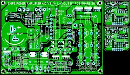
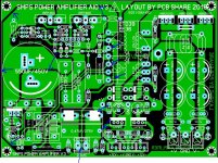
Lastly I marked the pcb at various points where the clearance should be larger.
Please note that between high and low voltages the clearance should not be less than 3mm if this cannot be achieved then a slot can be cut in the pcb.
If you look at a ATX power supply form a computer you will notice the clearances much better

SMPS clearances.JPG

Link for my smps testing for noise https://www.youtube.com/watch?v=KKjBy1pqhMM
 
Last edited:

xuantunt

Disabled
@Silvio

Thank you very much, I have learned a lot from your answer. I will try to modify as you say, I will update the information immediately after completion. When everything is the best I will provide pdf for everyone to consult.

Best regards!

Sorry for using google translate
 
Top