hi microsim,
i think you have seen it on ********.yes iam building lukas smps.there also iam looking for help.to confirm that iam going in the right direction
so that my first smps project desent get fail.that calculation is fully based on marty browns
280 watt half bridge example in power supply cookbook and also from practical switching
power supply design example.iam reading these books for around 5-6 months. spending
almost 6-7 hours a day .searching on the net for information.my hard disk space is almost full of
application notes and various smps,audio amplifier schematics.i didnt find the formula
on the net.as i already said iam following marty browns book theres a lot of mistakes in the printing.
the formulas are also messed up even the design examples have errors.i dont have any problem
sharing that stuff here if you allow me.i have seen you have deleted ******** from many posts in this forum.i knew the issues going
on.
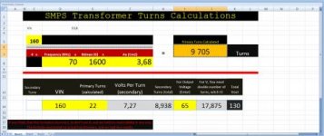
i have done a step by step transformer desin procedure.first i stuck on primary turns calcuation
coz it was half bridge my turns were far way off from the originals.again started reading different books
then i found in half bridge input voltae is divided by 2.then again right iam stuck on secondary turns
calculation.iam not sure the formula iam using is right or not.ill post all that stuff here.i have seen
knowledgable people not replying to those who know very little.i keep posting the the stuff i find usefull
over here.how can i comment on the stuff i dont know about.iam trying to gain as muvh as possible from
you people.there are some people willing to help including you.
thanks a lot for all your help.ill post the whole calculation over here
including the schematics and pcb.
best regards
ravs
be a vegeterian
i think you have seen it on ********.yes iam building lukas smps.there also iam looking for help.to confirm that iam going in the right direction
so that my first smps project desent get fail.that calculation is fully based on marty browns
280 watt half bridge example in power supply cookbook and also from practical switching
power supply design example.iam reading these books for around 5-6 months. spending
almost 6-7 hours a day .searching on the net for information.my hard disk space is almost full of
application notes and various smps,audio amplifier schematics.i didnt find the formula
on the net.as i already said iam following marty browns book theres a lot of mistakes in the printing.
the formulas are also messed up even the design examples have errors.i dont have any problem
sharing that stuff here if you allow me.i have seen you have deleted ******** from many posts in this forum.i knew the issues going
on.
i have done a step by step transformer desin procedure.first i stuck on primary turns calcuation
coz it was half bridge my turns were far way off from the originals.again started reading different books
then i found in half bridge input voltae is divided by 2.then again right iam stuck on secondary turns
calculation.iam not sure the formula iam using is right or not.ill post all that stuff here.i have seen
knowledgable people not replying to those who know very little.i keep posting the the stuff i find usefull
over here.how can i comment on the stuff i dont know about.iam trying to gain as muvh as possible from
you people.there are some people willing to help including you.
thanks a lot for all your help.ill post the whole calculation over here
including the schematics and pcb.
best regards
ravs
be a vegeterian
Last edited:
")