SMPS Transformer Primary Turns Calculations

papel12300

New member
Hi! microSim

Thank you! MicroSim. For you answer, I'll consider it for an upcoming project, in fact, found that a large number of articles, the writers prefer to work with half the Bmax, recommended by the manufacturers.
** Until next time ... ((@
 

thameesha7

New member
Dear Friends,

I have EI33 transformer bobbin i need make 12v to 230v switch mode inverter using this bobbin i need help for do this i don't know how calculate primary and secondary turns
and i don't know how select coil SWG value can some one help me please
thanks .
 

daniel002

New member
Hi thameesha7 ,

First of all you need to decide what smps topolgy you want to use , depending on your output power . The primary and secondary number of turns depend strongly on your input voltage range and what topology is beeing used. The wire size depends on the output current and sometimes switching frequency. (for low freq you may use magnet wire and for high freq litz wire).
If you can provide more details like output power, I can make a sugestion regarding smps topology to use and give you some app notes.

All the best,
Daniel
 

thameesha7

New member
Hi thameesha7 ,

First of all you need to decide what smps topolgy you want to use , depending on your output power . The primary and secondary number of turns depend strongly on your input voltage range and what topology is beeing used. The wire size depends on the output current and sometimes switching frequency. (for low freq you may use magnet wire and for high freq litz wire).
If you can provide more details like output power, I can make a sugestion regarding smps topology to use and give you some app notes.

All the best,
Daniel


Thanks Daniel for your reply
i realy need lightup 20w 230v CFL using 12v battery and 24v battery i mean i need 2 circuits
1) 12v battery to light up 230v 20w CFL
2) 24v battery to light up 230v 20w CFL
i have no idea about smps topology i need low cost and best way for make 2 of this circuits can you do it for me
thanks.
 

daniel002

New member
For this project, I think the best suited is a Flyback design. Depending on the series production estimated quantity(if intended to be produced in large quantity) , it may be cheaper if you chose to make a wide range input smps. This means that you can use the same board with 12V as well 24V.
 

daniel002

New member
Hi Dimonis,

This app note shows how to drive the bulb directly. I was thinking that thameesha7 wants to be power an CFL based economic light-bulb (the kind that you buy it from supermarket). In this case there is already a SMPS inside but you need to provide the 230V from the 12 or 24V battery. If is so, I think you just need to boost the voltage, that's way I sugested a Fly-back. The bulb has a rectifier at the input , so shouldn't be any problem if is supplyed with high voltage DC.
If he want's to power the tube directly, your push-pull ideea doesn't look bad.

Daniel.
 

thameesha7

New member
Hi Dimonis,

This app note shows how to drive the bulb directly. I was thinking that thameesha7 wants to be power an CFL based economic light-bulb (the kind that you buy it from supermarket). In this case there is already a SMPS inside but you need to provide the 230V from the 12 or 24V battery. If is so, I think you just need to boost the voltage, that's way I sugested a Fly-back. The bulb has a rectifier at the input , so shouldn't be any problem if is supplyed with high voltage DC.
If he want's to power the tube directly, your push-pull ideea doesn't look bad.

Daniel.

Sir Daniel002
i think you are correct if i bought 230v 20w cfl from super market with warranty i need lightup it without modification in the cfl circuit
cfl circuit get 230v sinewave ac voltage and it is convert to 230v dc voltage so i give it to any other wave like square wave it is convert to dc so i need to stepup voltage to lightup this 20w cfl
i make like this one
http://2.bp.blogspot.com/-l6r98vFc_...ght-circuit-diagram-12V-6V-10W-20W-design.jpg
but it only can lightup 11w cfl i don't know what is the theory of this circuit. is this flyback circuit ?
can you tell me about flyback theory and give me a way to do my project
thanks
 

daniel002

New member
Hi thameesha7 ,

The schematic from your link it looks like a forward for me with a kind of self-oscilating circuit.
This link is a simple flyback that can fit in your application...You can also use a dedicated fly-back controller (ex NCP1308, ICE2QR0665 etc) , this will probaly simplify your schematic.
http://danyk.cz/dcdc_en.html

Attached you can find two app notes that describes a step by step fla-back design.

Daniel.
 

Attachments

  • AN-4137.pdf
    399.9 KB · Views: 232
  • AN-Flyback_ST.pdf
    449.3 KB · Views: 301

Dimonis

New member
In this case there is already a SMPS inside but you need to provide the 230V from the 12 or 24V battery. If is so, I think you just need to boost the voltage, that's way I sugested a Fly-back.
HeHe ? I got you ! I began with this nonsense 15years ago , no good to use 2 SMPS.
A fly-back is hard to make from such low voltage , low efficiency and require current & voltage feedback , precision calculation of transformer.
Non-regulated push-pull is much easier , much reliable to make .
 

daniel002

New member
Dimonis, you are right, an open loop it may be easyer to design. Also a push-pull will use the core much better.
Still, if this SMPS needs to be for a wide range input 12-24V you need to have a closed loop. I think a fly-back for this power range (20W) , with closed loop, it is not a bad choice. Regarding efficiency, I an bot shure if the push-pull wil be much better.

Daniel.
 

Dimonis

New member
if this SMPS needs to be for a wide range input 12-24V
Not exactly 12-24 , but 12 or 24V it seems . :anonymous:
A push-pull with a switching windling maybe?

A fly-back is good when you need constant/limited current . I have such , made for charging a 24V battery from a car 12V.

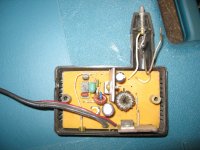
zaryad2.jpg

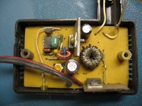
zariyad1.jpg
 
Last edited:

daniel002

New member
You should post your schematic . With a switching winding, an open loop design can work.
For up to 100W the fly-back is the most comon topology used in industry wherever you need constant current (battery charger), constant voltage or both combined. The reason for this is the cost and straight forward design.

Daniel.
 

thameesha7

New member
ok i don't need 12v to 20w cfl at this time but i need 24v to 20w cfl so there no voltage range now can you give me a way for do this job flyback or push pull or other topology but low cost
 

Virus

New member
Hi there, as they say the new bull in the camp has the shortest horns, ( so I'll tread lightly for a start )

I have some questions re: a SMPS that I am working on, 12v to 550v :"::

1. do I need to start a new thread with all my questions?, or can I just carry on from here.?

Thanks

Theunis
 

MicrosiM

Administrator
Staff member
Hi there, as they say the new bull in the camp has the shortest horns, ( so I'll tread lightly for a start )

I have some questions re: a SMPS that I am working on, 12v to 550v :"::

1. do I need to start a new thread with all my questions?, or can I just carry on from here.?

Thanks

Theunis

Yes you can start a new thread, feel free to use the forums without any limits :D
 
Top