SMPS transformer design tool

smps_fan

New member
Hi the secondary wire isn´t bigger than the primary one because there is written 0.11mm x 18 and that means that you have the 0.11mm wire 18 times in parallel
and only one strand of 0.4mm wire for secondary. 0.11mm 18 times is bigger than just one strand 0.4mm wire. You have to see 0.11mm wire as added diameter because it´s in parallel. You can´t use just one big piece of primary wire because of skin effect, if you thought why the program uses 0.11mm 18 times it´s the skin effect that makes all things worse.
 
Last edited:

Dimonis

New member
Pls also clarify what is 18 and 1.
I am unable to understand this,because if 0.11 is diameter,then how is secondary diameter > primary diamter ?
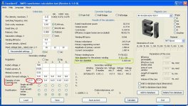
x18 , x1 - its the amount of strands (wires) in parallel .
The program doesn't calculate the wire diameter (gauge) , you must put it manually , according to which wire you have in stock. (marked red)
The program only suggests , what wire skin diameter is due to selected frequency . (marked green)

SMPS design.JPG
 

Dimonis

New member
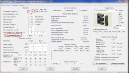
And why do you use such small flux density ? Tap the " recomended settings " button , and the prog will calculate the optimal flux for your core material.smps.JPG
 

phaedrus

Member
Because :
1) The material is from Cosmo Ferrites and I am not sure about the Flux Density.
2) I was reading
http://ludens.cl/Electron/Magnet.html
"You really need the core manufacturer's data, to determine how much flux density is acceptable. To give you a rough idea, first consider that at these frequencies almost always ferrite material is used. And ferrite saturates at about 0.3 to 0.4T, so this will be the absolute limit. For typical power-type ferrite material, at 25kHz you will have to keep the flux density below 0.15T, and at 100kHz below 0.05T. But a lot depends on core size too. A larger core will have to run at lower flux density in order to avoid overheating. "
Since this is a prototype,I was being conservative.
 

smps_fan

New member
Thank you for the tips Dimonis after playing around with your program I think I understand it better now. Very nice made but I have one question for 33khz couldn´t there be used up to 0.7mm wire as well ? I calculated the skin depth for 33khz with about 0.35mm which I see as the radius of the wire, so if I take the diameter that would make 0.7mm wire but I only have 0.6mm which should be good too. Right ?
 

Venture

New member
Hi Dimonis,

Great program, but I have a couple of questions.

1. For the transformer cores, the program doesn't explain about the gapped and un-gapped type of cores. Does this make a difference?
2. I'd like to use Litz wire in my transformer, and looking online I can see Litz wire has 14% greater diameter than normal copper wire. When I use Litz wire, should I manually add 14% to the diameter or leave it as before (number if strands x cross-sectional area). I'm thinking that Litz wire is a little thicker because each strand is shielded, but the actual copper current-carrying cross section is just like a normal wire.
3. Some of my transformers are coming out with winding-fill greater than 0.3, like 0.4-0.5. Is this okay and will it fit on to the core?

Sorry if these questions are stupid, but i'm just learning! Thanks!
 

Dimonis

New member
1. For the transformer cores, the program doesn't explain about the gapped and un-gapped type of cores. Does this make a difference?
2. I'd like to use Litz wire in my transformer, and looking online I can see Litz wire has 14% greater diameter than normal copper wire. When I use Litz wire, should I manually add 14% to the diameter or leave it as before (number if strands x cross-sectional area). I'm thinking that Litz wire is a little thicker because each strand is shielded, but the actual copper current-carrying cross section is just like a normal wire.
3. Some of my transformers are coming out with winding-fill greater than 0.3, like 0.4-0.5. Is this okay and will it fit on to the core?
1. The transformers in fact cannot have a gap , the more permeability of the core - the best for transformer . But the gap decreases the magnetic permeability . ( :abnormal: abnormal : The flyback transformer is not a transformer in it's practical realization , it's an inductor with coupled windings)
So this program designs only transformers for two-stroke converters.
2.3. The calculation of the cross sectional area of the winding is approximate . And depends on : how you manage to wind , what core former you use , etc. And better the experienced way .;)
 

Venture

New member
Thanks for the explanation Dimonis. I did a little reading last night about the topologies and found out that a gap isn't used for HB.

Here's another question for you...

If the program wants me to have an odd number of primary turns (let's say 23) and I wish to use a split primary (half under the secondary and half on top), is it okay to for those split primaries to have an unequal number of turns? I am guessing the answer is yes, unless you wish to tap the primary in the centre for some reason. You just split the primaries for better performance (coupling), right?

And why is a maximum fill factor of 0.3 recommended if it's okay to use more? I have never wound an SMPS trafo before so not sure if winding physically gets a lot harder after 0.3 or it's an electrical issue.
 
Last edited:
You can make the filling more than 0.3, but I repeat my answer:
With a large window filling the leakage inductance get more, it's bad.
 

Dimonis

New member
Any idea about the split primary winding question I asked?

Yes , it's a good solution . This way of winding decreases leakage inductance , so you may use larger filling factor.

PS Look at the transformers from PC ATX SMPS , they are wound "to the top" , i.e. maximum filling ! And they have split windings.
 
Top